Embedded chemotherapy pump with positive-pressure function

A function and pump body technology, applied in the field of embedded chemotherapy pump, can solve the problems of leakage, unsuitable fixation of puncture needle, treatment failure, etc., and achieve the effect of no heparin sealing tube, simple structure and clear effect.

Inactive Publication Date: 2010-02-10
张亚根
View PDF6 Cites 2 Cited by
  • Summary
  • Abstract
  • Description
  • Claims
  • Application Information

AI Technical Summary

Problems solved by technology

The current chemotherapy pumps must be sealed with heparin solution during use, and the operation of pulling out the needle while injecting is also required. In this way, the heparin solution is inevitably injected into the subcutaneous tissue. One of the causes of tissue inflammation and redness
[0004] 2. There is a safety risk of puncture window leakage
In this way, first, the puncture needle should not be fixed, and there is a chance of shaking (which will cause damage to the puncture window); then, the puncture needle tip can easily touch the bottom surface of the chemotherapy pump, causing barbs or burrs to appear on the needle tip, thereby damaging the puncture window when the needle is pulled out. (easy to cause leakage); in addition, the puncture windows are all circular with a diameter of about 1 cm, and the needles are required to be in the center (and the puncture windows will bear up to hundreds of times of acupuncture in actual use), so Concentrated and high-frequency acupuncture is also a cause of leakage
[0005] 3. It is very easy to block the pipeline and lead to treatment failure
However, due to the failure to fundamentally solve many practical problems in the use of chemotherapy pumps, the device technology of chemotherapy pumps still remains at a relatively primitive level.
That is to say: At present, there is no chemotherapy pump technology that can completely solve the above-mentioned problems in China.

Method used


Image

  • Embedded chemotherapy pump with positive-pressure function
  • Embedded chemotherapy pump with positive-pressure function

Examples


Embodiment Construction

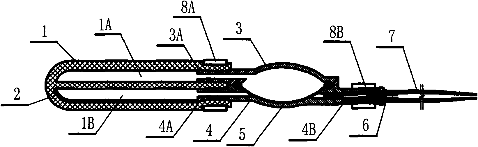
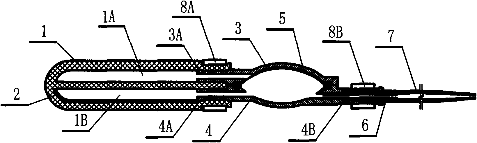
[0018] Depend on figure 1 It can be seen that the present invention consists of four parts: a chemotherapy pump body, a positive pressure valve, a treatment pipeline and a connecting piece. Among them: the chemotherapy pump body is composed of a puncture tube 1 and a backing plate 2; the positive pressure valve is composed of an upper valve housing 3, a lower valve housing 4 and a membrane 5; the treatment pipeline is independently composed of a treatment tube 7; The cable tie 8A and the rear cable tie 8B are composed.

[0019] Chemotherapy pump body: the puncture tube 1 has a partition in the middle, an upper cavity 1A and a lower cavity 1B inside, and a circular elastic puncture-resistant body that communicates with the outside world at one end. The puncture tube 1 can allow the puncture needle to puncture in an oblique direction and go to multiple points along the axis of the puncture tube 1 . The puncture tube 1 can allow a puncture needle to penetrate into its upper cav...


PUM


Abstract

The invention relates to an embedded chemotherapy pump with positive-pressure function, comprising a chemotherapy pump body, a positive-pressure valve, a treatment pipeline and a connecting piece. Thechemotherapy pump body comprises a puncture pipe and a liner plate; the positive-pressure valve comprises an upper valve shell, a lower valve shell and a membrane which is an elastic pipe internallyprovided with an upper cavity and a lower cavity; the upper valve shell is an upwards concave shell and is matched with a liquid inlet pipe and a liquid outlet pipe which are also connected with bothends of the lower valve shell, i.e. a downwards concave shell; the membrane is a reversible concave elastomer, is arranged in a cavity formed by the upper valve shell and the lower valve shell and separates the cavity into an upper cavity and a lower cavity; and the upper cavity of the puncture pipe is communicated with the cavity formed by the upper valve shell and the membrane to form a closed positive-pressure adjusting cavity the liquid volume of which can be adjusted to realize the positive-pressure flushing and pipe-sealing requirements when transfusion is finished.

Description

technical field [0001] The invention relates to a medical device for infusing liquid, in particular to an embedded chemotherapy pump with positive pressure function which is widely used in treating cancer. Background technique [0002] In cancer treatment, especially for chemotherapy of malignant tumors, embedded chemotherapy pump technology has been widely used. Its notable feature is that through the subcutaneous implantation (puncture) window and connecting pipeline, the chemotherapy drugs are directly applied to the tumor occurrence area, thereby increasing the blood concentration of the drug in the diseased tissue. It is a powerful means for the treatment of cancer and malignant tumors today, and has the advantages of high therapeutic targeting, small side effects, long-term administration, and good patient comfort. However, due to the deficiencies in the design of the current chemotherapy pump, the following defects and deficiencies exist in its clinical use: [0003...

Claims


Application Information

Patent Timeline
Patent Type & Authority Applications(China)
IPC IPC(8): A61M31/00
Inventor 张亚根
Owner 张亚根
Why Eureka
Try Eureka