Method for obtaining circuit delay time in ultrasonic measuring device

A technology of circuit delay and measurement device, applied in the field of ultrasonic measurement, can solve the problem of inability to obtain the propagation time of ultrasonic signals

Inactive Publication Date: 2010-02-10
NINGBO UNIV +1
View PDF0 Cites 17 Cited by
  • Summary
  • Abstract
  • Description
  • Claims
  • Application Information

AI Technical Summary

Problems solved by technology

[0004] In the ultrasonic measuring device, people pay more attention to the propagation time of the ultrasonic signal in the physical medium, but the total time from the si

Method used


Image

  • Method for obtaining circuit delay time in ultrasonic measuring device
  • Method for obtaining circuit delay time in ultrasonic measuring device
  • Method for obtaining circuit delay time in ultrasonic measuring device

Examples


Embodiment 1

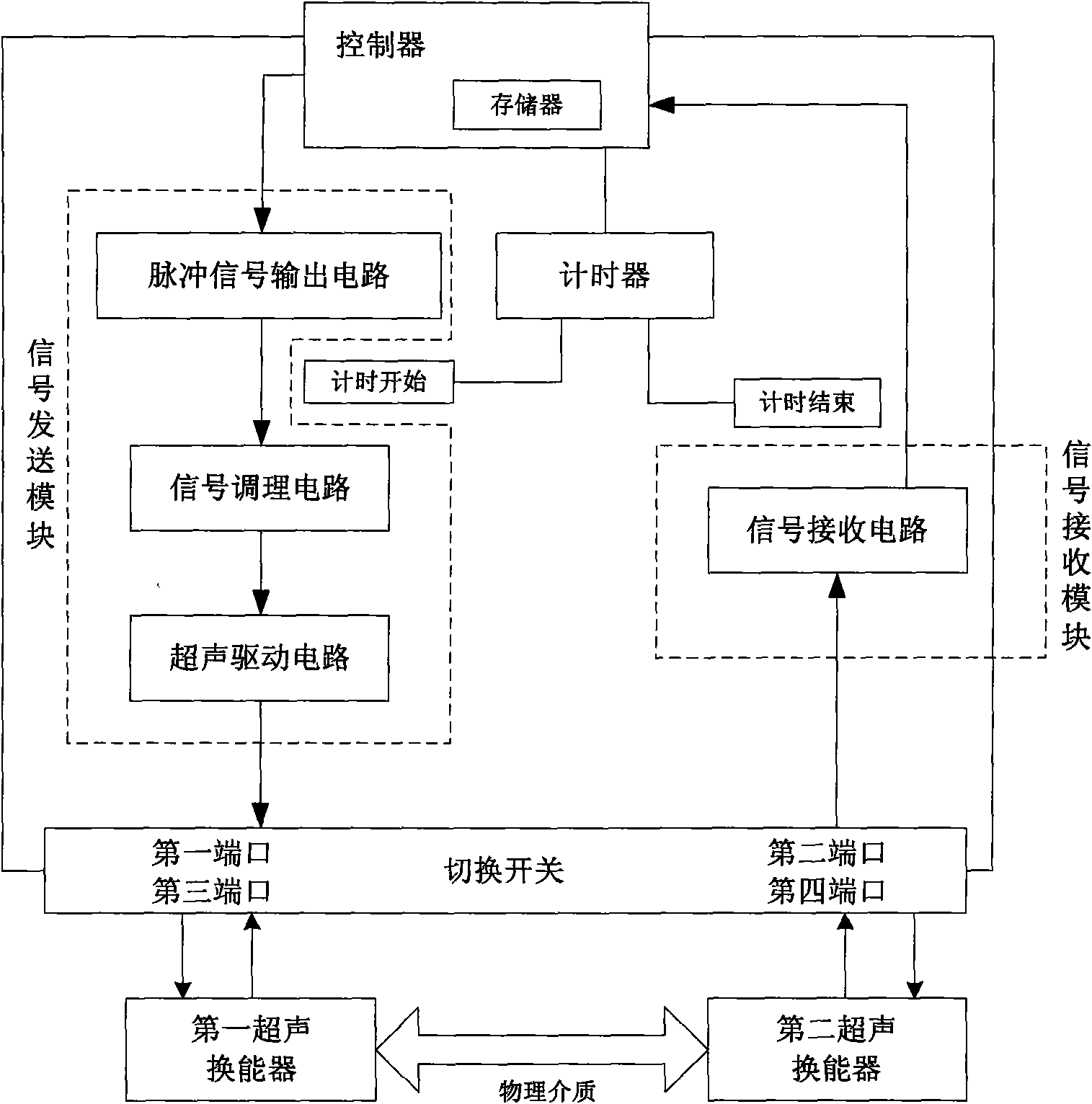
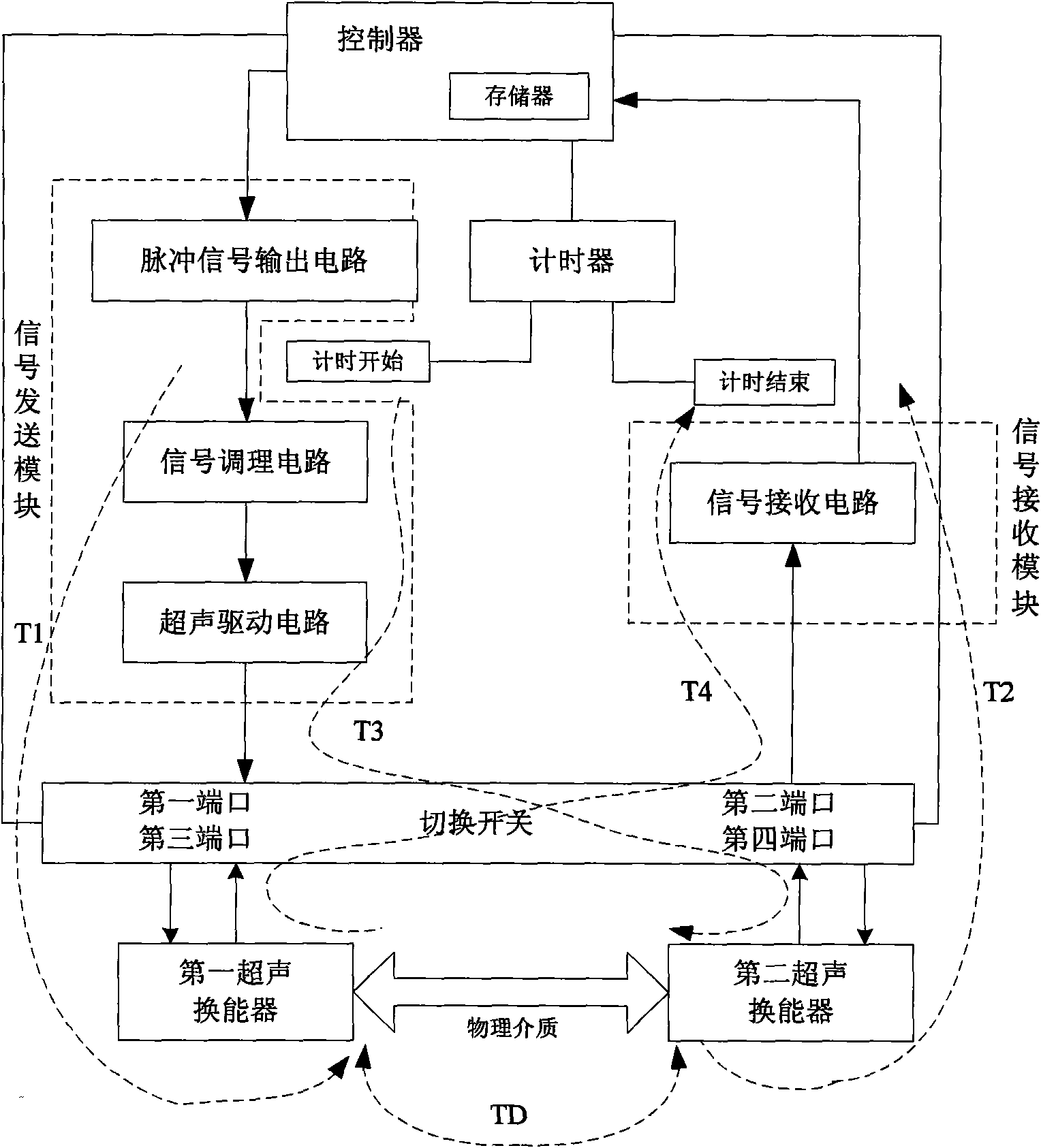
[0030] Embodiment 1: The ultrasonic measuring device includes a controller, a timer, a signal sending module, a signal receiving module, a switch, a first ultrasonic transducer and a second ultrasonic transducer, and the signal sending module is mainly output by sequentially connected pulse signals circuit, signal conditioning circuit and ultrasonic driving circuit, the signal receiving module is mainly composed of signal receiving circuit, the switch has a first port, a second port, a third port and a fourth port, the controller is equipped with a memory, the controller is respectively Connected with the timer, pulse signal output circuit, signal receiving circuit, and switch, the controller controls the timer to start timing or end timing, and read the count value in the timer after the timer ends and store the count value in the memory , the controller controls the pulse signal output circuit to output the excitation pulse signal, the controller reads the pulse signal extrac...

Embodiment 2

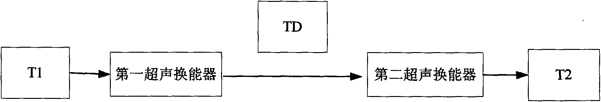
[0047] Embodiment 2: Repeat the steps ①~⑩ described in Embodiment 1 N times to realize the same measurement of N groups, and obtain the equation A 11 = T 1 + TD + T 2 A 21 = T 3 + TD + T 4 A 31 = T 1 + 2 TD + T 4 ...


PUM


Abstract

The invention discloses a method for obtaining circuit delay time in an ultrasonic measuring device. The method has the following advantages of: by using the characteristic that a first ultrasonic energy converter and a second ultrasonic energy converter can send an ultrasonic signal and receive the ultrasonic signal, controlling the switching on and the switching off among four ports of a selector switch by a controller; realizing the sending and the receiving of the ultrasonic signals with five different modes; and respectively obtaining five different total times by a timer; and obtaining the circuit delay time by combining with the format of the each total time through the minimum square law, thereby being capable of obtaining the propagation time of the ultrasonic signal in physical medium. Furthermore, the method has simple computing process and more accurate circuit delay time.

Description

technical field [0001] The invention relates to an ultrasonic measurement technology, in particular to a method for obtaining circuit delay time in an ultrasonic measurement device. Background technique [0002] Ultrasonic rangefinders, ultrasonic flowmeters, etc. are currently commonly used ultrasonic measuring devices. Ultrasonic rangefinders send out ultrasonic signals through the transmitting transducer and are reflected by obstacles, received by the receiving transducer, and propagated in the medium by the ultrasonic signal The distance between the ultrasonic distance meter and the obstacle can be calculated by the time of this period and the speed of the ultrasonic wave in the medium; the ultrasonic flowmeter mainly calculates the instantaneous flow by obtaining the liquid flow velocity in the pipeline, so as to achieve the purpose of flow measurement, and The flow velocity of the liquid in the pipeline is obtained by indirect calculation of the propagation time of the...

Claims


Application Information

Patent Timeline
IPC IPC(8): G01S15/08G01F1/66G01H17/00
Inventor 孙广清姚灵王让定徐云陈昌根王亚华祝向辉
Owner NINGBO UNIV
Why Eureka
Try Eureka