
Coaxial separator

A separator, coaxial technology, applied in the field of separation, which can solve problems such as gas-solid or gas-liquid separation

Inactive Publication Date: 2010-02-17
CISDI ENG CO LTD
View PDF0 Cites 6 Cited by
  • Summary
  • Abstract
  • Description
  • Claims
  • Application Information

AI Technical Summary

Problems solved by technology

Through this coaxial separator, the problem of gas-solid or gas-liquid separation in the fluid can be solved

Method used


Image

  • Coaxial separator
  • Coaxial separator
  • Coaxial separator

Examples


Embodiment Construction

[0011] The specific embodiment of the present invention will be further described below in conjunction with accompanying drawing:

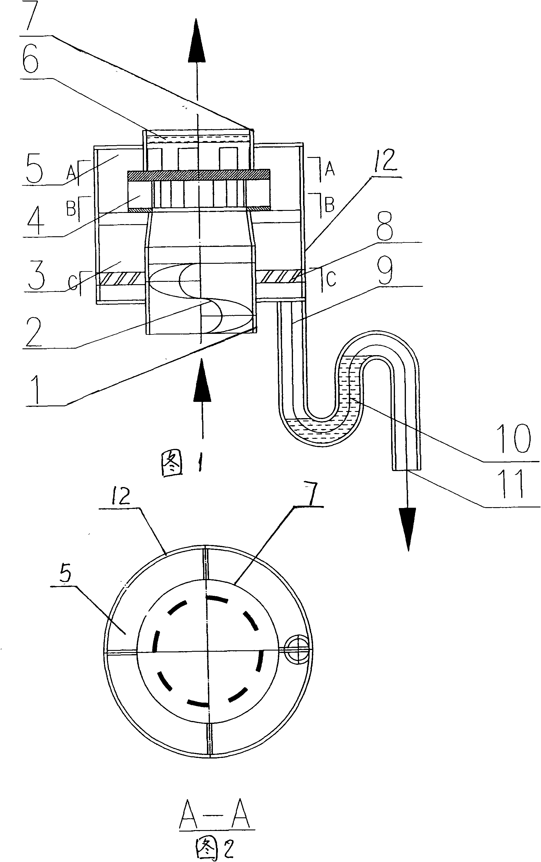
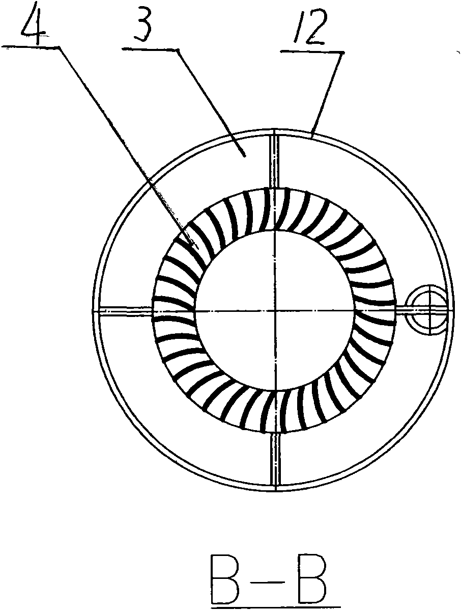
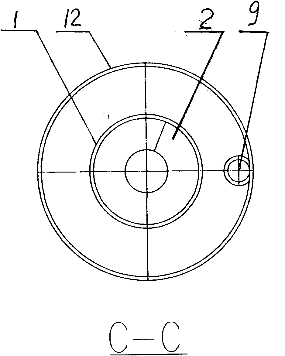
[0012] The swirl guide vane 2 is installed in the fluid inlet pipe 1, and the separator swirl area 4 is installed at the outlet of the fluid inlet pipe 1; between the fluid inlet pipe 1 and the separator shell 12, the liquid swirl guide vane 8 and the liquid outlet pipe are installed at the bottom. 9 and U-shaped liquid air seal pipe 10, the top is equipped with defoaming layer 6 and exhaust pipe 7.

[0013] When the fluid of the two media enters from the fluid inlet pipe 1 at the lower part of the equipment, it is pre-swirled through the swirl guide vane 2 to make the fluid rotate, and the swirling fluid enters the cyclone separator blade area 4 through the narrow annular slot High-speed centrifugal separation is carried out, and the liquid and gas are separated into the liquid separation zone 3, and then further separated by the liquid swirl gui...


PUM


Abstract

The invention belongs to the technical field of separation, and relates to a coaxial separator. A rotational flow guide vane is arranged in a fluid inlet pipe, and the outlet of the fluid inlet pipe is provided with a separator rotary vane area; and between the fluid inlet pipe and a separator shell, the lower part is provided with a liquid rotational flow guide vane, a liquid outlet pipe and a U-shaped liquid air seal pipe, and the top part is provided with a defoaming layer and an exhaust pipe. The coaxial separator has significant effects, is suitable for fluid separation in small pipes, and is particularly suitable for an emergency diffusion pipe of a dry type gas tank.

Description

technical field [0001] The invention belongs to the technical field of separation and relates to a coaxial separator. Background technique [0002] In separation equipment, gas-liquid separation is very common, and its equipment such as cyclone separators are well known, such as XLT type, XLT / A type, B type, E type bypass type, diffusion type, long cone type, Multi-tube, tornado cyclone dust collector, etc., and cyclone separator in the steam drum of the boiler, etc. These devices have a common feature, that is, the fluid enters from the tangential direction, and the flow rate of the fluid is required: for the dust collector, it is 15m / s~20m / s, and we are talking about the cyclone separator in the steam drum of the boiler, the fluid flows from The tangential speed is required to be 5m / s~8m / s. In engineering practice, we encountered the following problem: when the gas holder is released in an emergency, the gas will bring out a lot of gas holder sealing oil, which not only ...

Claims


Application Information

Patent Timeline
IPC IPC(8): B01D45/16B04C5/00
Inventor 程杰
Owner CISDI ENG CO LTD
Features
  • Generate Ideas
  • Intellectual Property
  • Life Sciences
  • Materials
  • Tech Scout
  • Unparalleled Data Quality
  • Higher Quality Content
  • 60% Fewer Hallucinations
Learn More