
Tapered roller type drive wheel hub bearing unit

A tapered roller and wheel hub technology, applied in the field of tapered roller drive wheel hub bearing units, can solve the problems of high vehicle risk, serious accidents, loose bearing inner ring, etc., and achieve improved bearing capacity and reliable operation Sexuality, not easy to early failure, and weaken the effect of stress concentration

Active Publication Date: 2011-12-28
ZHEJIANG ZHAOFENG MECHANICAL & ELECTRONICS CO LTD
View PDF0 Cites 0 Cited by
  • Summary
  • Abstract
  • Description
  • Claims
  • Application Information

AI Technical Summary

Problems solved by technology

[0003] However, the existing improvements are all carried out on the outer ring of the hub bearing. Since the inner ring of the unit is combined with the outer ring and rolling elements, the tolerance accuracy, rotation accuracy and clearance standards to be achieved are very high, especially for bearings. The accurate control of the internal clearance directly affects the bearing capacity, life reliability and vibration noise of the unit, so the improvement of the inner ring structure of the tapered bearing is quite complicated and difficult; The vehicle load and road conditions change complicatedly, so that in the fault statistics of the hub bearing unit, especially the lack of bonding strength between the inner ring of the bearing and the flange mandrel causes loosening, which poses the greatest danger to the vehicle
Analyzing the reasons, the combination of the two bearing inner rings and the flanged mandrel in the existing products mainly depends on the interference fit between the shaft holes, and the ball cage of the universal joint of the transmission system is pressed and fixed. Once the ball cage is loose, the inside of the bearing will The ring may loosen, resulting in a vicious accident

Method used


Image

  • Tapered roller type drive wheel hub bearing unit
  • Tapered roller type drive wheel hub bearing unit
  • Tapered roller type drive wheel hub bearing unit

Examples


Embodiment Construction

[0015] The specific embodiments of the present invention will be further described below in conjunction with the accompanying drawings.

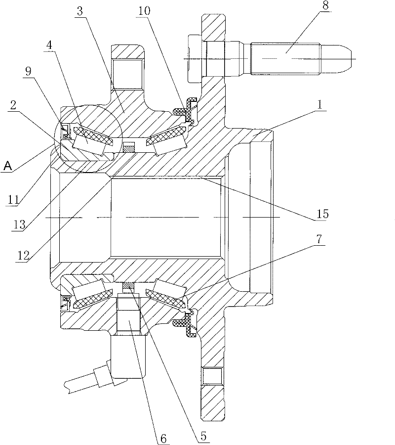
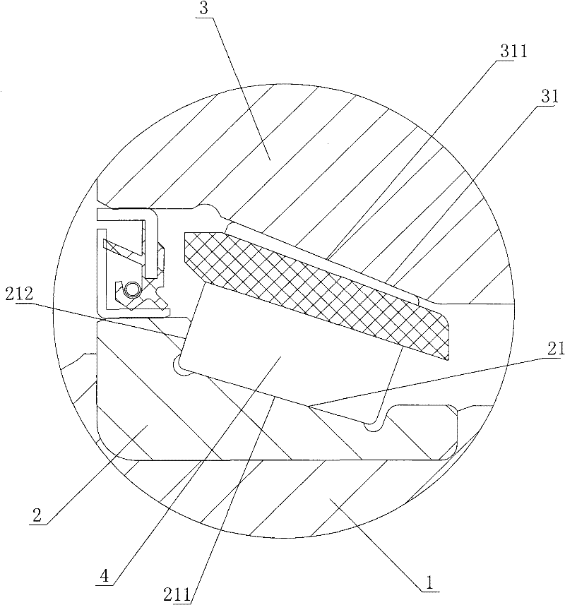
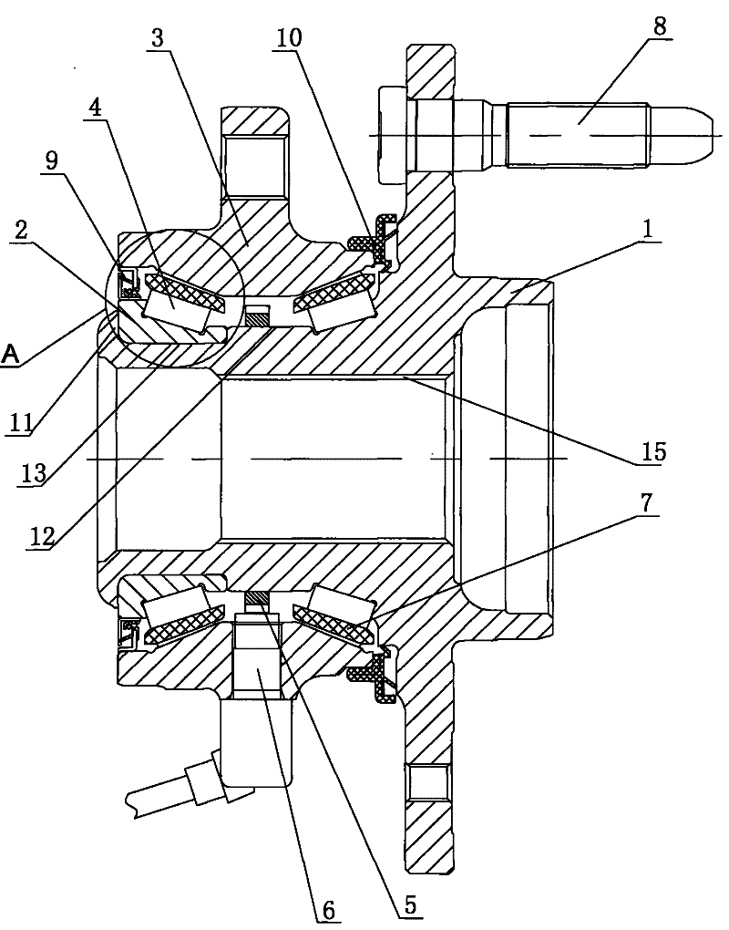
[0016] figure 1 and figure 2 Shown is the tapered roller type driving wheel hub bearing unit of the present invention, which includes a flange shaft 1, an inner ring 2, an outer ring 3 and a tapered roller 4. The end of the flange shaft 1 is provided with a curling 11, and the The neck of the flange shaft 1 is provided with a step 12, and the curling 11 fixes the inner ring 2 on the journal 13 between the curling 11 and the step 12 through positioning riveting, and the inner ring 2 and the step 12 of the neck of the flange shaft 1 are each provided with a row of outer raceways 21, the outer ring 3 is provided with an inner raceway 31 corresponding to the outer raceway 21, and the outer raceway 21 is connected to the outer raceway 21 A cage 7 is arranged between the inner raceways 31, and the tapered rollers 4 are divided into two and asse...


PUM


Abstract

The invention discloses a tapered roller drive wheel hub bearing unit which comprises a convex edge shaft, an inner ring, an outer ring and a tapered roller, wherein the inner ring and the convex edgeshaft are respectively provided with a row of outer rolling paths; inner rolling paths corresponding to the outer rolling paths are arranged in the outer ring; isolines at the bottom surfaces of theouter rolling paths are convex curves, and isolines of the inner rolling paths are convex curves. Because the technical scheme is adopted, and the isolines of the main carrying surfaces of the bearingrolling paths are the convex curves, the invention ensures that the stress along the effective contact length of the tapered roller and the main carrying surfaces of the rolling paths is uniformly distributed in a normal load; when in a ponderosity load or the roller generates deflection, the stress concentration of both ends of the rolling contact surface can be eliminated or weakened, thereby enabling the hub bearing unit to be difficult to generate early failure, and effectively improving the carrying capability and the running reliability of the drive wheel hub bearing unit.

Description

technical field [0001] The invention relates to an automobile chassis part, in particular to a tapered roller type drive wheel hub bearing unit. Background technique [0002] Due to their high radial and axial load carrying capacity at the same time, tapered rolling bearings are widely used in the slewing bearings of (loaded) commercial vehicle wheels - hub bearings. The traditional commercial wheel hub bearing is composed of two sets of tapered roller bearings inserted into the flange plate, and then inserted into the flange mandrel to form a wheel hub bearing unit; it was later improved to use a set of double row tapered roller bearings inserted into the flange. disc, and then inserted into the flanged mandrel to form a hub bearing unit; at the beginning of this century, the outer ring of the double-row tapered bearing and the flanged disc were integrated to form a flanged outer ring, and the inner rings of the two bearings were still sleeved. into the flanged mandrel to ...

Claims


Application Information

Patent Timeline
Patent Type & Authority Patents(China)
IPC IPC(8): F16C19/38F16C33/58F16C33/76
CPCF16C19/386F16C33/581F16C2326/02
Inventor 孔爱祥周守虎康乃正
Owner ZHEJIANG ZHAOFENG MECHANICAL & ELECTRONICS CO LTD
Learn More