Bearing assembly for machine table with magnetic load relieving mechanism

A bearing device, the technology of magnetic bearings, applied in the direction of bearings, bearings, shafts and bearings of rotary motion

Inactive Publication Date: 2010-02-17
SCHAEFFLER TECH AG & CO KG
View PDF6 Cites 6 Cited by
  • Summary
  • Abstract
  • Description
  • Claims
  • Application Information

AI Technical Summary

Problems solved by technology

The disadvantage of this embodiment of the permanent magnets is that, when the rotor moves relativ...

Method used


Image

  • Bearing assembly for machine table with magnetic load relieving mechanism
  • Bearing assembly for machine table with magnetic load relieving mechanism
  • Bearing assembly for machine table with magnetic load relieving mechanism

Examples


Embodiment Construction

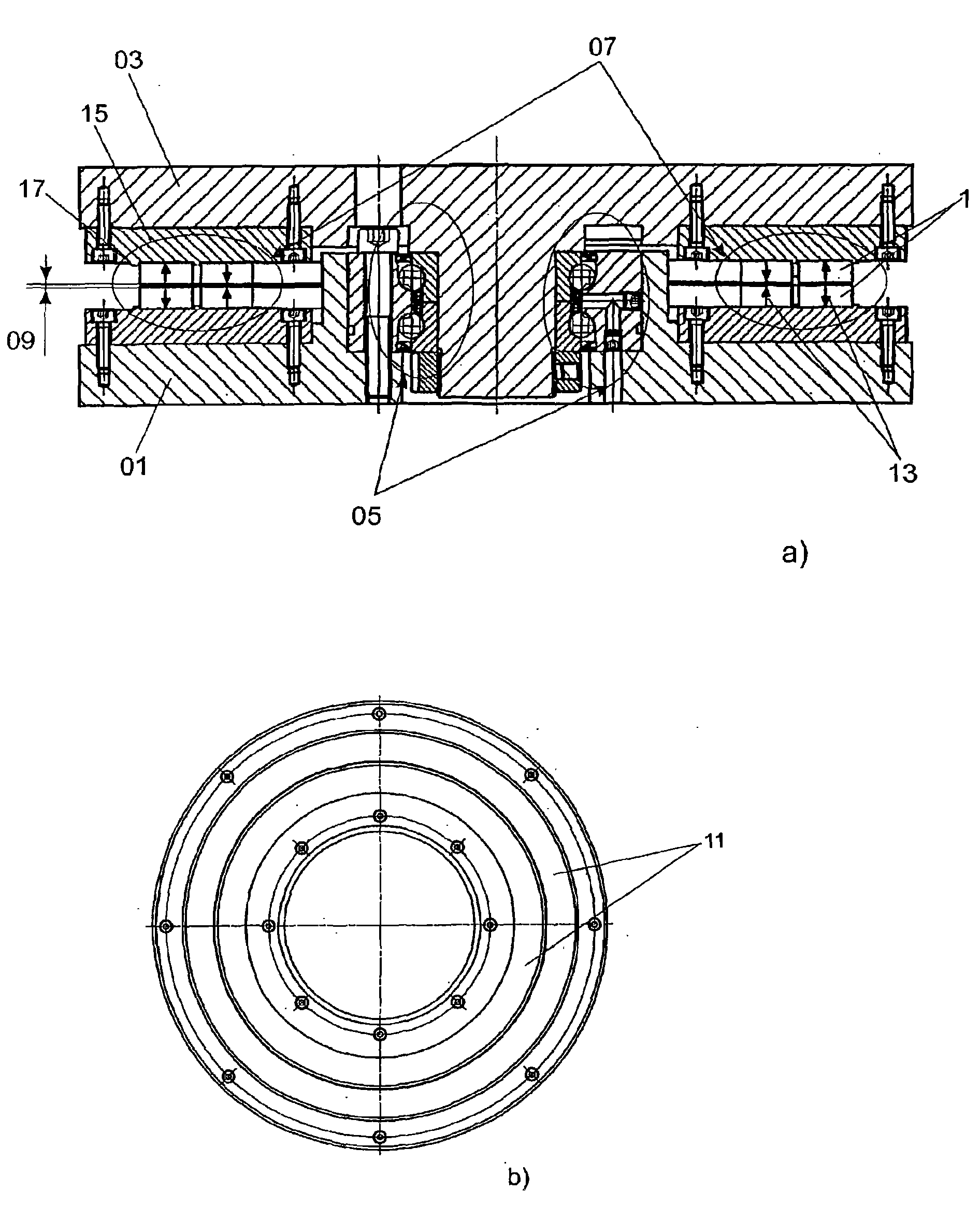
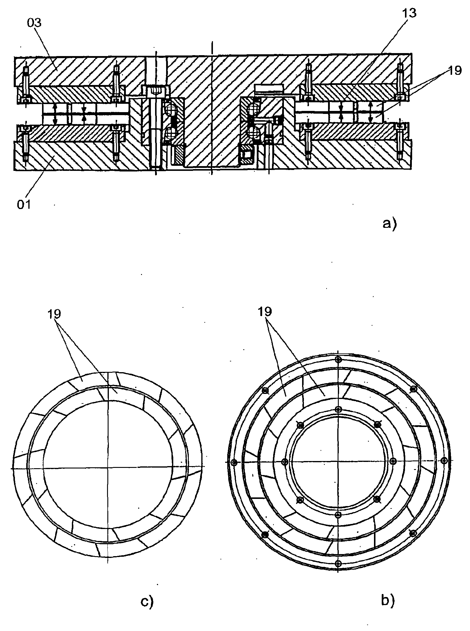
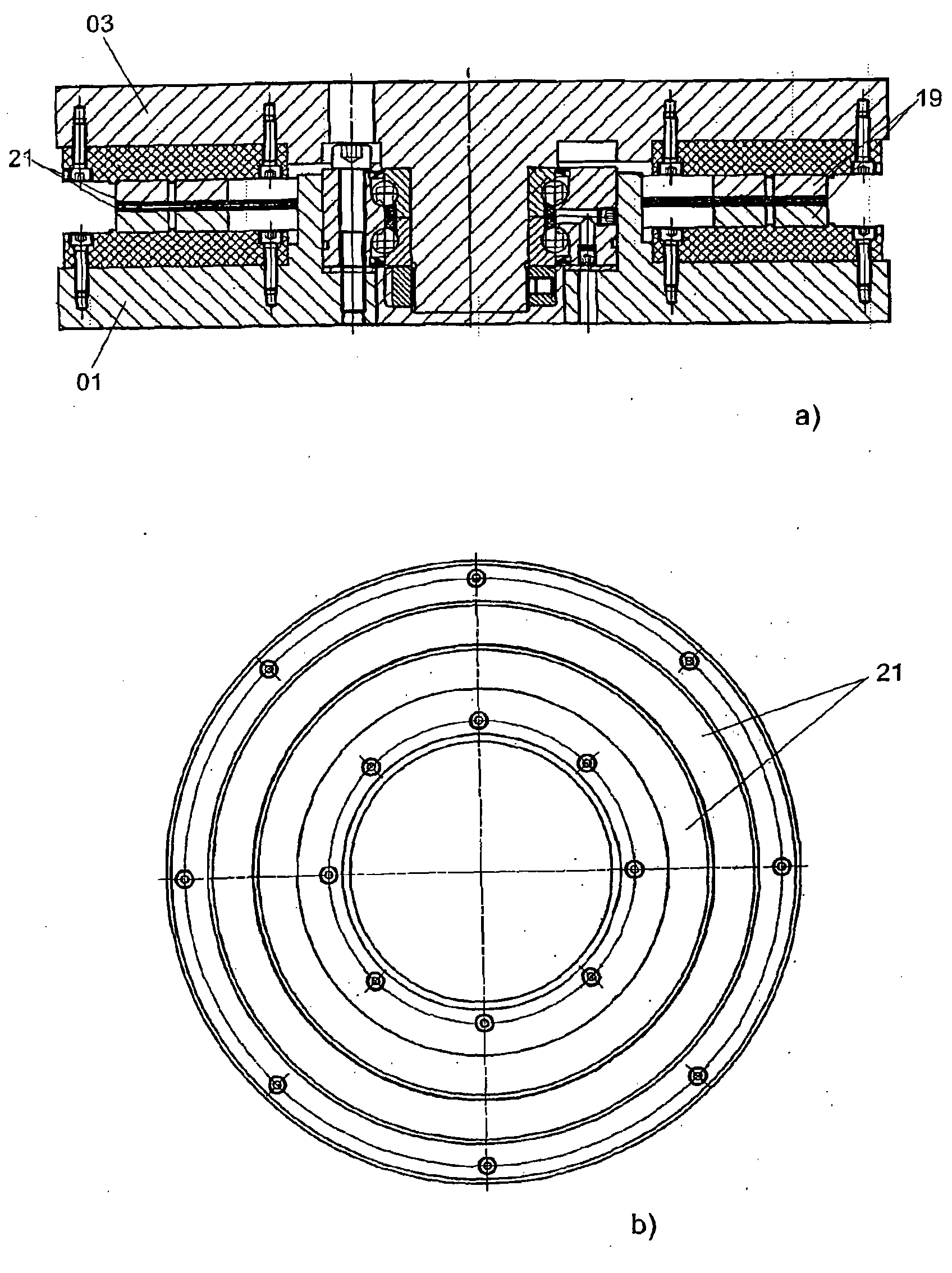
[0024] figure 1 a) shows a sectional view of a first embodiment of a bearing arrangement for a machine table with a stator 01 and a rotor 03 mounted movably relative to the stator. The support takes place via the rolling bearing 05 and the magnetic bearing 07 , which unloads the rolling bearing 05 by magnetic repulsion forces. The two component bearings are designed as swivel bearings, wherein a double row angular contact ball bearing is provided as rolling bearing 05 . As an alternative, cylindrical ball bearings or radial / axial roller-cylindrical bearings are preferably considered.

[0025] The rotor 03 is supported movably relative to the stator 01 via a rolling bearing 05 . The magnetic bearing 07 is arranged radially outside the rolling bearing 05, and has a stator permanent magnet group fixed on the stator and an opposite rotor permanent magnet group fixed on the rotor. The stator permanent magnet group and the rotor permanent magnet group pass through the air gap 09 ...


PUM


Abstract

The invention relates to a bearing assembly for a machine table, which has a stator (01) and a runner (03) relatively supported to the stator, the bearing assembly has a roller bearing (05) and a magnet bearing (07) forcing the roller bearing by magnetic repulsive force to be removed. The magnet bearing (07) has a stator permanent magnetic group arranged on the stator (01) and a runner permanent magnetic group which is opposite to the stator permanent magnetic group and arranged on the runner (03), wherein, two opposite permanent magnetic groups are partitioned by an air gap (03), and have same magnetic poles at mutually faced side surfaces. The field strength equalizing units are provided, which compensate for the magnetic field strength fluctuations arising between the opposite permanentmagnetic groups in the movement of the runner.

Description

technical field [0001] The invention relates to a bearing arrangement for a machine table according to the preamble of claim 1 . Background technique [0002] The machine table according to the invention has a stator and a rotor mounted movably relative to the stator. The bearing device includes a rolling bearing and a magnetic bearing that unloads the rolling bearing through magnetic repulsion force, and the magnetic bearing has at least one stator permanent magnet group arranged on the stator and at least one rotor permanent magnet group oppositely arranged on the rotor. Two opposing sets of permanent magnets are separated by an air gap and have the same magnetic poles on sides facing each other. [0003] Such a bearing arrangement is designed in particular as a cylindrical bearing with integrated magnetic relief. Other possible fields of use are passive magnetic bearings with bearing blocks or emergency-running bearings and cylindrical bearings in which gravity and stat...

Claims


Application Information

Patent Timeline
IPC IPC(8): F16C32/04F16C39/06
CPCB23Q2220/004F16C19/184F16C39/066F16C2322/00F16C2322/39
Inventor 金特·施密特赖纳·帕次瓦尔德
Owner SCHAEFFLER TECH AG & CO KG
Why Eureka
Try Eureka