Pressing device capable of aligning lens with lens barrel and pressing method thereof

A technology of pressing device and lens, applied in installation, optics, instrument and other directions, can solve the problems of reducing assembly accuracy, assembly failure rate, pressing alignment deviation, etc., and achieve the effect of improving assembly pass rate and precise assembly.

Inactive Publication Date: 2010-02-17
ART CONTROL SYST LNC
View PDF0 Cites 13 Cited by
  • Summary
  • Abstract
  • Description
  • Claims
  • Application Information

AI Technical Summary

Problems solved by technology

[0003] When the lens 10 is placed in the extraction tray 201, there is a large gap between the receiving groove of the extraction tray 201 and the lens 10, so that the lens 10 cannot be effectively positioned in the extraction tray 201. Therefore, when the transfer device When the suction nozzle 211 of 21 picks up the lens 10 and transfers it to the carrier 221 of the assembly station 22, the lens 10 and the lens barrel 11 are not absolutely aligned in the center position, but the lens 10 is directly pressed and positioned on the lens barrel by the suction nozzle 211 When it is within 11, it will cause a deviation in the press-fit alignment, and the lens 10 cannot be positioned smoothly, thereby greatly reducing the accuracy of assembly
[0004] Due to the deviation of the alignment between the lens 10 and the lens barrel 11, when the suction nozzle 211 directly presses the lens 10 into the lens barrel 11, the peripheral edge of the lens 10 will rub against the inner ring surface of the lens barrel 11. Scratches, and scraped debris in the lens barrel 11, which not only affects the accuracy of assembly, but also leads to the failure rate of assembly

Method used


Image

  • Pressing device capable of aligning lens with lens barrel and pressing method thereof
  • Pressing device capable of aligning lens with lens barrel and pressing method thereof
  • Pressing device capable of aligning lens with lens barrel and pressing method thereof

Examples


Embodiment Construction

[0035] In order to make your examiners make a further understanding of the present invention, hereby give a preferred embodiment and cooperate with the drawings, the description is as follows:

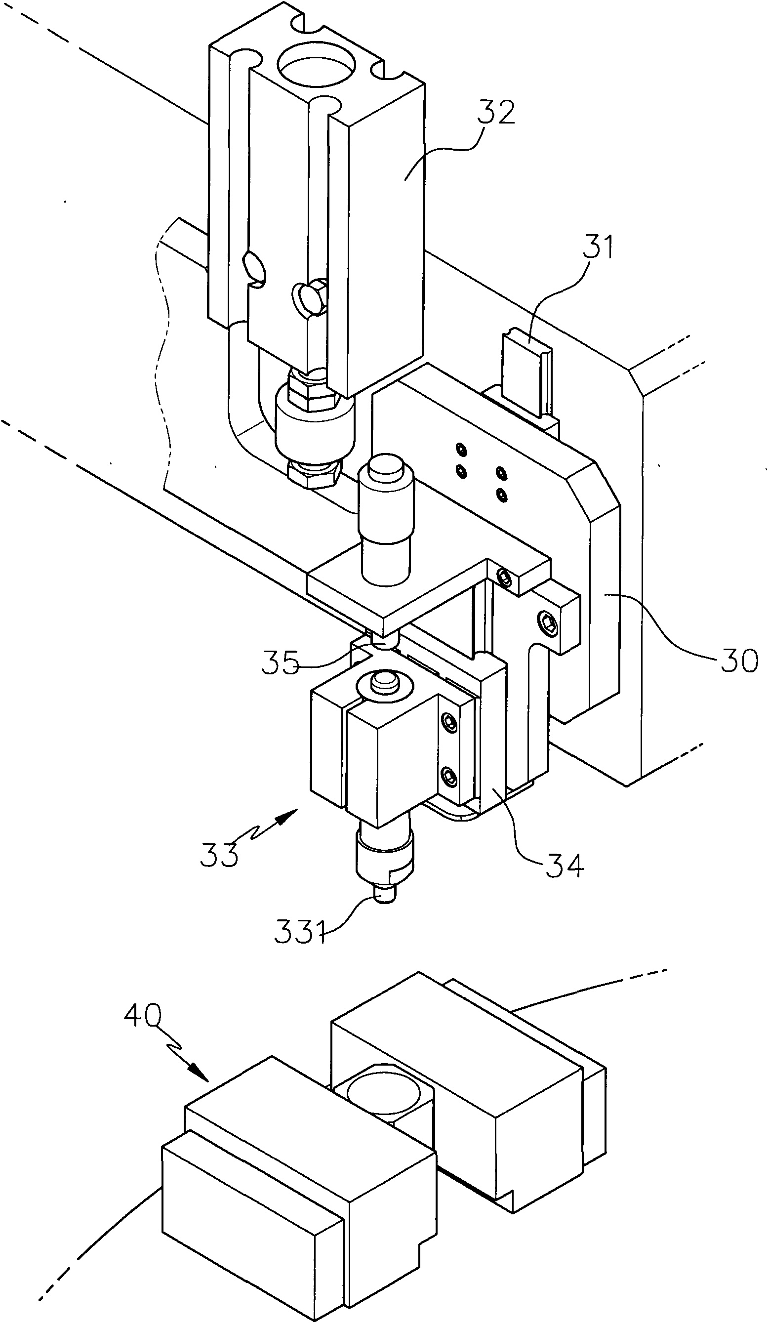
[0036] see image 3 , Figure 4 As shown, the present invention is provided with a sliding seat 30 connected with a lifting mechanism. The lift driving source 32 of the seat 30 is used to drive the sliding seat 30 to perform a lifting action, wherein the lifting driving source 32 can be a pressure cylinder, and a pressing group 33 is installed on the sliding seat 30, so the The pressing group 33 is provided with a pressing head 331 which can be used as a lens pick and place device, and a floating mechanism is arranged between the pressing group 33 and the sliding seat 30. The floating mechanism is to connect the pressing group 33 to another sliding rail group 34. It is slidably arranged on the sliding seat 30, so that the pressing head 331 of the pressing group 33 can move up and dow...


PUM


Abstract

The invention discloses a pressing device capable of aligning a lens with a lens barrel and a pressing method thereof. A pressing group is assembled on a sliding seat which can be driven to lift, andis provided with a pressure head on which the lens can be placed and from which the lens can be taken; a floating mechanism is arranged between the pressure head and the sliding seat so as to make thepressure head and the sliding seat relatively lift and slide; and a bearer bears the lens barrel with a guiding part and the lens barrel is transferred to a position below the pressing group so as toperform segmented pressing operation on the lens and the lens barrel; and the pressing way is that: the sliding seat and the pressing group are driven to descend first, the pressure head of the pressing group can stop descending by means of the floating mechanism immediately when the lens is contacted with the guiding part of the lens barrel so as to enable the pressure head to slightly press thelens, and at the same time, the pressure head is driven to perform repressing after the guiding part of the lens barrel is aligned with the lens so as to press and position the lens into the lens barrel, so the practicable effects of precise assembly and great improvement on assembly qualification rate can be achieved by utilizing the floating mechanism of the pressure head.

Description

technical field [0001] The invention relates to a floating mechanism using a pressure head, which can first lightly press the guide lens, and then accurately align the lens with the lens barrel, and then position the lens in the lens barrel by heavy pressure, so as to greatly improve the assembly accuracy. The invention relates to a pressing device for a lens guide and alignment lens barrel and a pressing method thereof. Background technique [0002] Nowadays, technological products are changing with each passing day, bringing people a lot of convenience, such as mobile phones, PDAs, digital cameras, etc. The described lens assembled in an automated manner includes a lens 10 and a lens barrel 11, and the assembly method is that a number of lenses 10 are mounted on the tray 201 of the feeding device 20, and a suction device 21 sucks. The nozzle 211 can suck the lenses 10 on the extraction tray 201 and transfer them to the top of the carrier 221 of the assembly station 22 . T...

Claims


Application Information

Patent Timeline
Patent Type & Authority Applications(China)
IPC IPC(8): G02B7/02
Inventor 丘于川
Owner ART CONTROL SYST LNC
Why Eureka
Try Eureka