
Miniature multifunctional cutting machine

A cutting machine, multi-functional technology, applied in the direction of forming/shaping machine, special forming/shaping machine, stone processing tools, etc., can solve the problems of low processing efficiency, high labor intensity, and unguaranteed processing quality, and achieve high precision , Assembly precise effect

Active Publication Date: 2015-07-29
张盛华
View PDF6 Cites 1 Cited by
  • Summary
  • Abstract
  • Description
  • Claims
  • Application Information

AI Technical Summary

Problems solved by technology

At present, there is no special equipment for stone and wood processing, only a separate hand-held cutting machine and grinding machine; when processing stone and wood, the worker fixes the stone with one hand and holds it with the other hand in a relatively flat place. Cutting machines or grinding machines are used for processing operations. This processing method has the following disadvantages: 1. There is usually no working platform for stone and wood processing at the construction site. Workers often squat on the ground for stone and wood processing, and rely entirely on the hand strength of the workers. To resist the horizontal thrust generated in the processing process, the labor intensity is high and the processing efficiency is low; 2. The processing process completely depends on the experience of the workers, and the processing quality cannot be guaranteed

Method used


Image

  • Miniature multifunctional cutting machine
  • Miniature multifunctional cutting machine
  • Miniature multifunctional cutting machine

Examples


Embodiment Construction

[0020] The invention will be further described in detail below in conjunction with the accompanying drawings and specific embodiments.

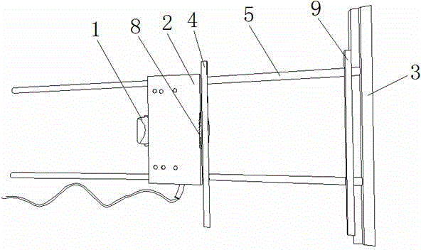
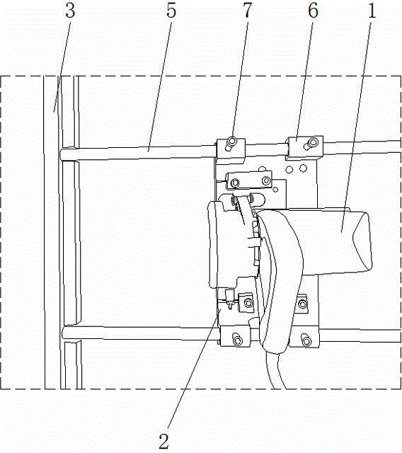
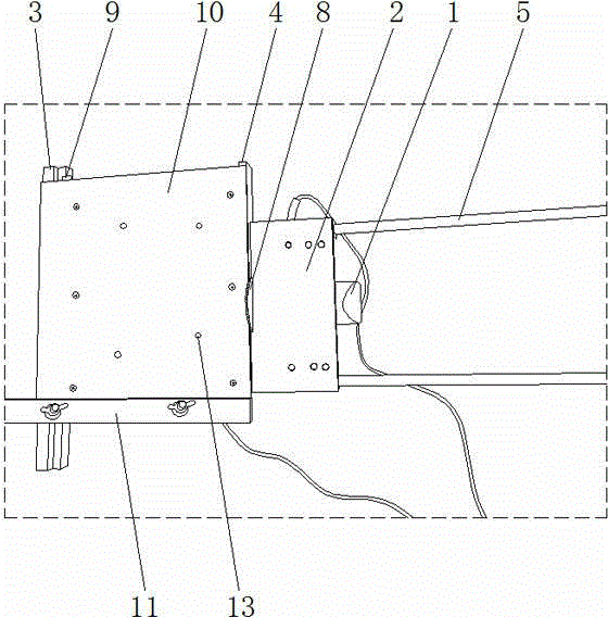
[0021] Such as figure 1 , 2 As shown, the micro multifunctional cutting machine includes a cutting machine body 1 and a cutting machine frame. The cutting machine frame includes a base plate 2 , a positioning base 3 , an adjustment positioning plate 4 , a reference plate 9 and two guide rails 5 . One end of two guide rails 5 is fixedly connected on the positioning base 3, and the two guide rails 5 are arranged parallel to each other. In this embodiment, the two guide rails 5 adopt circular steel pipes, and one end of the circular steel pipes is threaded on the positioning base Seat 3 on. The two sides of a board surface of the base plate 2 are respectively provided with guide sliding sleeves 6, and the guide sliding sleeves 6 on both sides of the base plate 2 are respectively sleeved on the guide rails 5 on the corresponding side and are s...


PUM


Abstract

The invention provides a miniature multifunctional cutting machine. A cutting machine rack comprises a base plate, a positioning base, an adjustment positioning plate and two guide rails, wherein the two guide rails are parallel to each other; guide sliding sleeves are arranged on two sides of a plate surface of the base plate respectively; the guide sliding sleeves on two sides of the base plate sleeve the guide rails on the corresponding sides respectively and are matched with the guide rails in a sliding manner; the adjustment positioning plate is arranged on the two guide rails, is propped against one side of the base plate and corresponds to the positioning base; a cutting machine body is fixedly connected onto one plate surface of the base plate; a cutting blade on the cutting machine body extends out of the other plate surface of the base plate and is perpendicular to the other plate surface of the base plate. The miniature multifunctional cutting machine can be used for cutting stones and woods of different sizes through adjusting the adjustment positioning plate on the two guide rails, cutting right-angle edges, bevel edges and chamfers of the stones and woods, so that an effect of one machine with a plurality of functions is achieved, the processing precision is higher, and the assembly of processed stones and woods is more precise.

Description

technical field [0001] The invention relates to a cutting machine, in particular to a miniature multifunctional cutting machine suitable for stone and wood processing. Background technique [0002] During the decoration construction process, it is necessary to cut and process the stone and wood on site to ensure that the size and shape of the stone and wood meet the requirements of on-site paving. At present, there is no special equipment for stone and wood processing, only a separate hand-held cutting machine and grinding machine; when processing stone and wood, the worker fixes the stone with one hand and holds it with the other hand in a relatively flat place. Cutting machines or grinding machines are used for processing operations. This processing method has the following disadvantages: 1. There is usually no working platform for stone and wood processing at the construction site. Workers often squat on the ground for stone and wood processing, and rely entirely on the...

Claims


Application Information

Patent Timeline
IPC IPC(8): B28D1/22B28D7/00B28D7/04B27C5/00
CPCB27C5/00B28D1/22B28D7/00
Inventor 张盛华
Owner 张盛华
Learn More