Liquid crystal display and manufacture method thereof

A liquid crystal display device and display area technology, applied in nonlinear optics, instruments, optics, etc., can solve problems such as uneven brightness, affecting the picture quality of liquid crystal display, and generating errors

Inactive Publication Date: 2010-02-17
AU OPTRONICS (SUZHOU) CORP LTD +1
View PDF0 Cites 2 Cited by
  • Summary
  • Abstract
  • Description
  • Claims
  • Application Information

AI Technical Summary

Problems solved by technology

Figure 1C It is a schematic diagram of the detection after the corner is squeezed and deformed, and the corner vertex 104 has moved out for a certain distance, resulting in an error
These errors lead to

Method used


Image

  • Liquid crystal display and manufacture method thereof
  • Liquid crystal display and manufacture method thereof
  • Liquid crystal display and manufacture method thereof

Examples


Embodiment Construction

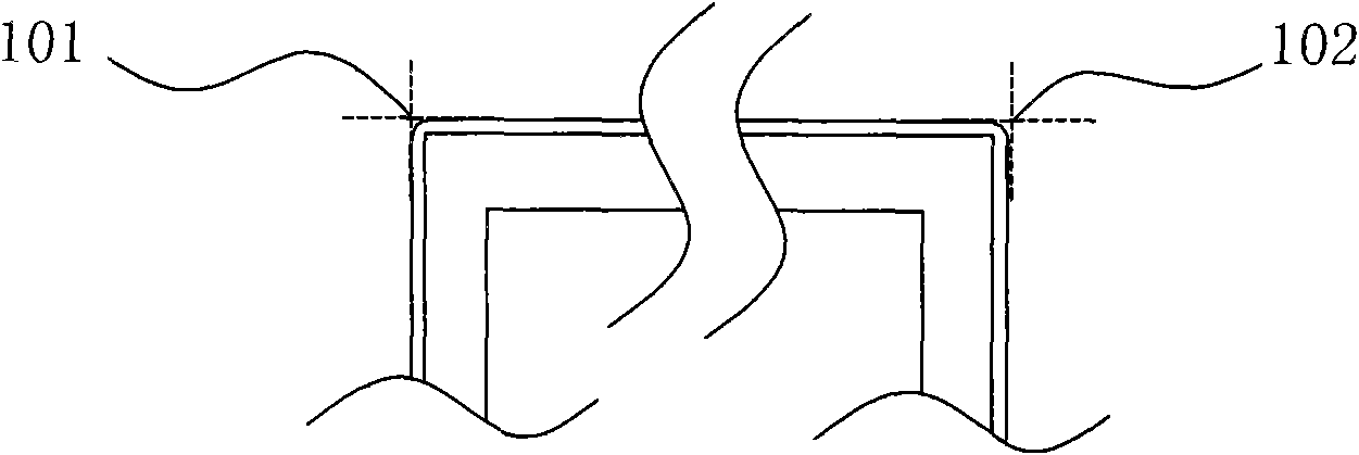
[0018] Please refer to figure 2 , figure 2 It is a schematic diagram of a backlight module according to an embodiment of the present invention. The backlight module 200 has a light emitting area 220 and an edge area 210 . The edge area 210 can be divided into a first side 211 , a second side 212 , a fourth side 213 and a third side (not shown in the figure). The first mark 201 is located on the second side 212, and the second mark 202 is located on the fourth side 213. To be precise, the first mark 201 is located on the top corner surrounded by the first side 211 and the second side 212. area, the second mark 202 is located in the corner area surrounded by the first side and the fourth side. It should be noted that the positions of the first mark and the second mark are not limited thereto, and any structure that can determine the positional relationship of the backlight module through these marks will be disclosed in the present invention.

[0019] In this embodiment, t...


PUM


Abstract

The invention discloses a liquid crystal display and a manufacture method thereof. The liquid crystal display comprises a display panel and a backlight module, wherein the display panel comprises a display zone and a light shading zone; the backlight module is arranged at the opposite side of the display panel and comprises a lighting zone and a marginal zone consisting of a first mark and a second mark. Production equipment which is provided by the manufacture method comprises a fixed pedestal, a sensing element, a control element and a loading element; the backlight module is fixed in the fixed pedestal; the sensing element senses the first mark and the second mark of the backlight module and outputs a sensing signal to the control element; the control element outputs a control signal tothe loading element according to the sensing signal; and the loading element clamps the display panel and move a certain distance according to the control signal so that the display panel and the backlight module are precisely assembled in a para-position way.

Description

technical field [0001] The present invention relates to a liquid crystal display device and its manufacturing method, in particular to a liquid crystal display device which can be precisely positioned and assembled and its manufacturing method. Background technique [0002] In recent years, flat panel display technology including liquid crystal display technology has been greatly developed, and has gradually replaced cathode ray tube (CRT) display technology. For a liquid crystal display device, since the liquid crystal display panel itself does not emit light, it usually has a display panel and a backlight module for illuminating the display panel. In the production process of the liquid crystal display, these two parts are manufactured separately and assembled together to form a complete liquid crystal display. Since the liquid crystal display is a very precise device, the alignment accuracy requirements are also very high during the assembly process of the display panel ...

Claims


Application Information

Patent Timeline
IPC IPC(8): G02F1/1333G02F1/13357
Inventor 史曙光
Owner AU OPTRONICS (SUZHOU) CORP LTD
Why Eureka
Try Eureka