Measuring tape finial mechanism and measuring tape thereof

A top-notch, tape measure technology, applied in the direction of bendable rulers, etc., can solve the problems of potential safety hazards, accidental injury to the human body, unfavorable packaging and transportation, etc., and achieve the effect of simple and reasonable overall structure and convenient setting

Active Publication Date: 2010-02-24
NINGBO GREAT WALL PRECISION INDAL
View PDF3 Cites 9 Cited by
  • Summary
  • Abstract
  • Description
  • Claims
  • Application Information

AI Technical Summary

Problems solved by technology

[0002] When measuring on the construction site, it is often necessary to fix one end of the tape before the measurement can be completed smoothly. Therefore, most of the tapes now have a top mechanism to fix one end, but the top structure we have seen so far is relatively simple

Method used


Image

  • Measuring tape finial mechanism and measuring tape thereof
  • Measuring tape finial mechanism and measuring tape thereof
  • Measuring tape finial mechanism and measuring tape thereof

Examples


Embodiment 1

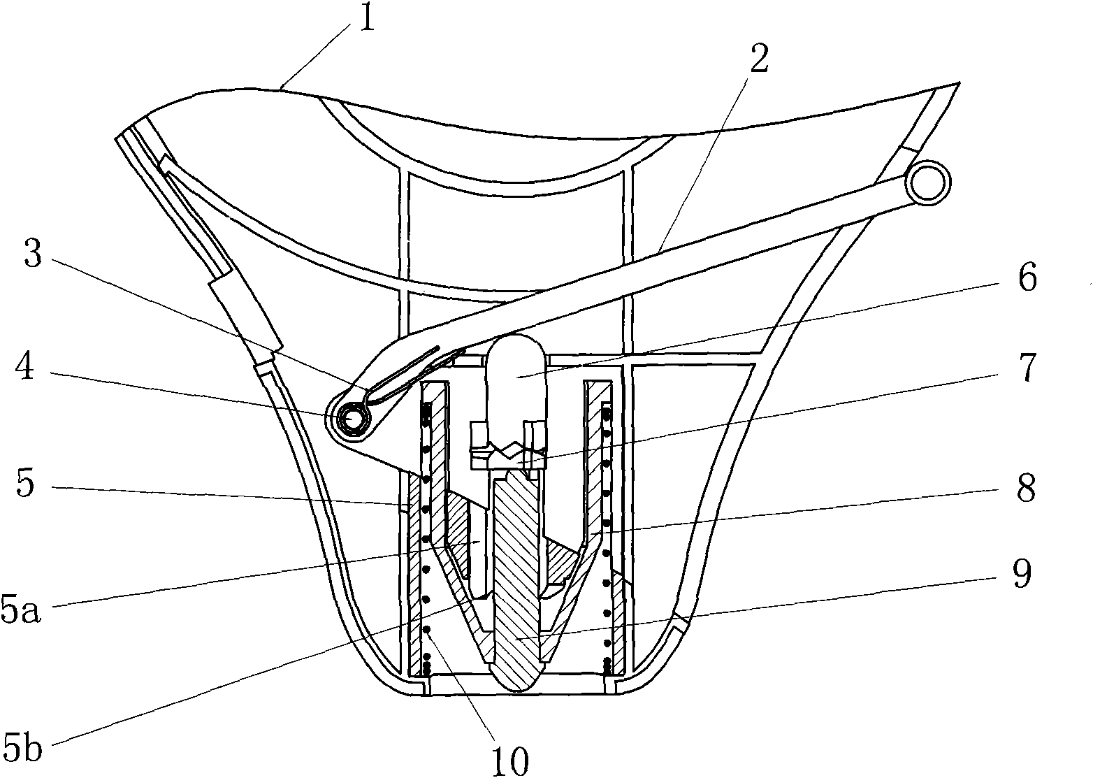
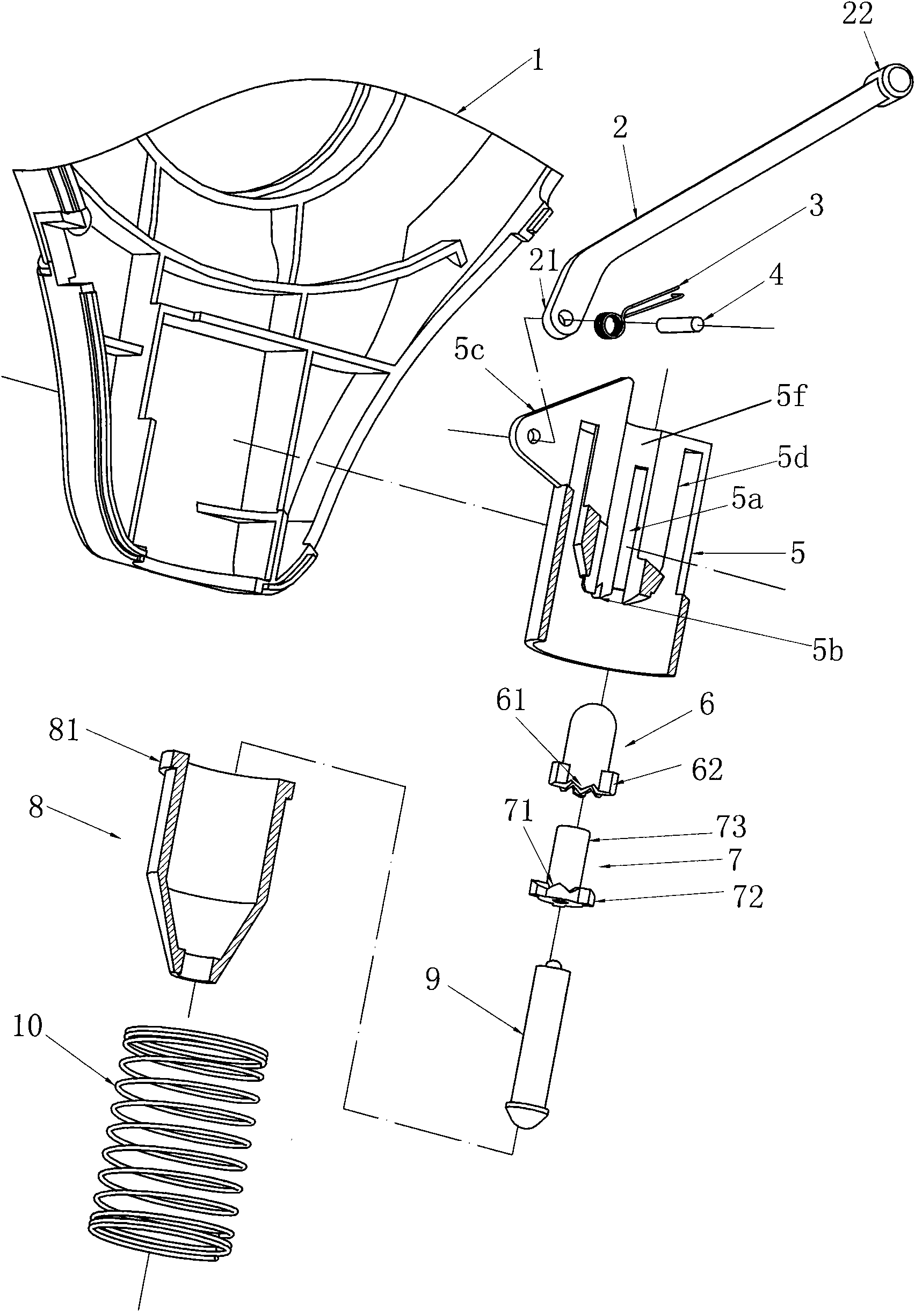
[0049] Example 1: Reference figure 1 , figure 2 , Figure 5 and Figure 6 As shown, a tape measure with a tip mechanism includes a scale case 100 , a casing 5 , an upper pusher 6 , a lower pusher 7 , a drive mechanism, a tip seat 8 , a reset member 10 and a tip 9 .

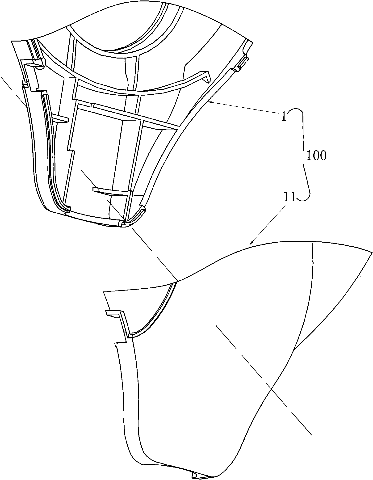
[0050] refer to image 3 As shown, the scale housing 100 is assembled from the regular scale housing 1 and the reverse scale housing 11, with a cavity in the middle for the top mechanism to accommodate, and a lip at the mouth.

[0051] The outer casing 5 is arranged in the scale housing 100, and has a raised cylinder 5d in the center. The center of the cylindrical 5d has a through hole 5f that runs through the outer casing 5. There is an axial slide rail 5a in the through hole 5f, and the lower end of the cylindrical 5d surrounds the through hole. A serrated first helical tooth 5b is formed. There is a pair of lugs 5c extending from the upper end of the outer casing 5, and a pivot pin 4 is arranged between t...

Embodiment 2

[0060] Embodiment 2, refer to Figure 7 As shown, the driving mechanism in the tape measure with the top mechanism in this embodiment includes a button 2, the button 2 is limited to the upper part of the outer cover, the lower end of the button 2 is in conflict with the upper end of the upper push piece, and a force button is arranged between the button and the outer cover. Reverse force reset elastic member 3a. In this embodiment, the return elastic member 3 a is a compression spring, and one end of the compression spring abuts against the button 2 , and the other end of the compression spring abuts against the inner wall of the casing 100 . Other structures are the same as in Embodiment 1.

Embodiment 3

[0061] Embodiment 3, refer to Figure 8 As shown, the driving mechanism in the tape measure with the top mechanism in this embodiment includes a horizontal pressing rod 2 limited in the scale housing and a return elastic member 3a that forces the pressing rod to be reversed. The middle part of the pressing rod 2 is connected to the The upper ends of the push-up parts are offset, and the other structures are the same as those in Embodiment 1.


PUM


Abstract

The invention relates to a measuring tape finial mechanism. The finial mechanism comprises a finial and is characterized by also comprising t a central convex column of a sheath, an upper push piece,a lower push piece, a finial seat and a restoration piece, wherein the column has a through hole penetrating the sheath, and the inside of the through hole has an axial slide rail; first skew gears are formed and distributed on the lower end of the column and around the through hole; the upper push piece is slidably arranged inside the through hole, and first ring gears are formed and distributedon the lower end of the upper push piece in circumferential direction; the first ring gears are radially provided with an outward first flange which is matched with the slide rail; the lower end of the lower push piece is propped on the finial, and the upper end is detachably connected with the upper push piece; moreover, second ring gears in division rotary fit with the first ring gears of the upper push piece are convexly formed and distributed on the lower end of the lower push piece in circumferential direction, and the outer circumferential wall of the lower end has second skew gears which are matched with the first skew gears of the lower end of the column; the second skew gears protrude outwards in radial direction to form a second flange in back-and-forth sliding fit with the sliderail inside the through hole to drive the mechanism; the finial seat is telescopically limited on the lower end of the sheath; the restoration piece extends outside the finial to fix the measuring tape when used, and retracts the finial into a measuring tape shell when not used to avoid causing injuries to people; and moreover, the total volume of the measuring tape is reduced, which is favorablefor packaging, transportation and storage.

Description

technical field [0001] The invention relates to a tip mechanism of a tape measure, and also relates to a tape measure equipped with the tip mechanism. Background technique [0002] When measuring on the construction site, it is often necessary to fix one end of the tape before the measurement can be completed smoothly. Therefore, most of the tapes now have a top mechanism to fix one end, but the top structure we have seen so far is relatively simple. Generally, the top is directly assembled on the scale shell, and the sharp end of the top is exposed outside, which may accidentally injure the human body, which has potential safety hazards. Moreover, the overall volume increases, which is not conducive to packaging and transportation. For example, the Chinese utility model patent "Tape Measure with Clutch Handle" (authorized announcement number: CN2722193Y) whose reference patent number is ZL200420066462.5, similarly also has the Chinese invention publication "Hand Mechanism o...

Claims


Application Information

Patent Timeline
IPC IPC(8): G01B3/10
Inventor 黄忠华张令辉
Owner NINGBO GREAT WALL PRECISION INDAL
Why Eureka
Try Eureka