
Grain condition detecting rod

A technology for detecting rods and grain conditions, which can be used in the fields of catching or killing insects, sampling devices, animal husbandry, etc. It can solve the negative pressure environment where it is difficult to extract pests, cannot continuously and reliably extract pests, and lower the space of insect traps Large and other problems, to achieve the effect of improving economic and social benefits, simple structure, and improving accuracy

Active Publication Date: 2010-02-24
ZHENGZHOU XINSHENG ELECTRONICS TECH
View PDF1 Cites 27 Cited by
  • Summary
  • Abstract
  • Description
  • Claims
  • Application Information

AI Technical Summary

Problems solved by technology

However, when sucked by the sucking tube, because the space of the lower trapping tube is large, it is not easy to form a negative pressure environment for extracting pests, so the pests cannot be extracted continuously, reliably and quickly.
In addition, impurities are easily mixed in the extracted pests, resulting in inaccurate counting

Method used


Image

  • Grain condition detecting rod
  • Grain condition detecting rod
  • Grain condition detecting rod

Examples


Embodiment approach 1

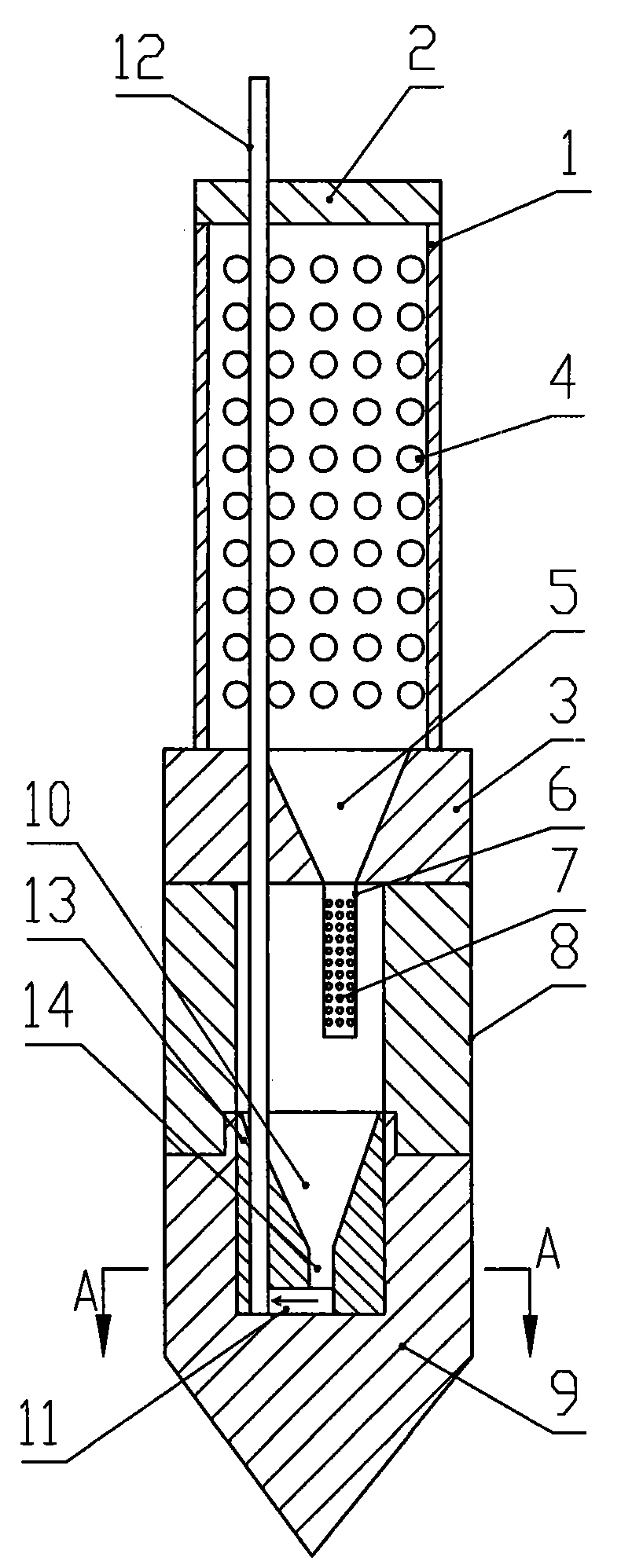
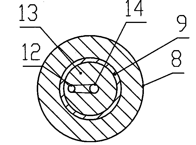
[0029] Such as figure 1 , 2 As shown, the present invention includes an insect trap rod 1 , the upper end of the insect trap rod 1 is connected with a plug 2 , and the lower end of the insect trap rod 1 is connected with a joint 3 . Insect trap rod 1 is a hollow rod, evenly distributed with trap holes 4 on the rod, and the center line of trap holes 4 is inclined downward with the axis of trap rod 1 to have an angle, so that dust and impurities are difficult to enter when pulling out. The diameter of the trap hole 4 is smaller than the particle size of the grain but larger than the size of the pests to be captured.

[0030] A funnel 5 is provided in the middle of the joint 3, and the wall of the funnel 5 is smooth to prevent pests from climbing up along the wall. The lower end of the funnel 5 is fixedly connected with an impurity separation pipe 6, the impurity separation pipe 6 is hollow and sealed at the bottom, and a number of separation holes 7 are evenly arranged on the ...

Embodiment approach 2

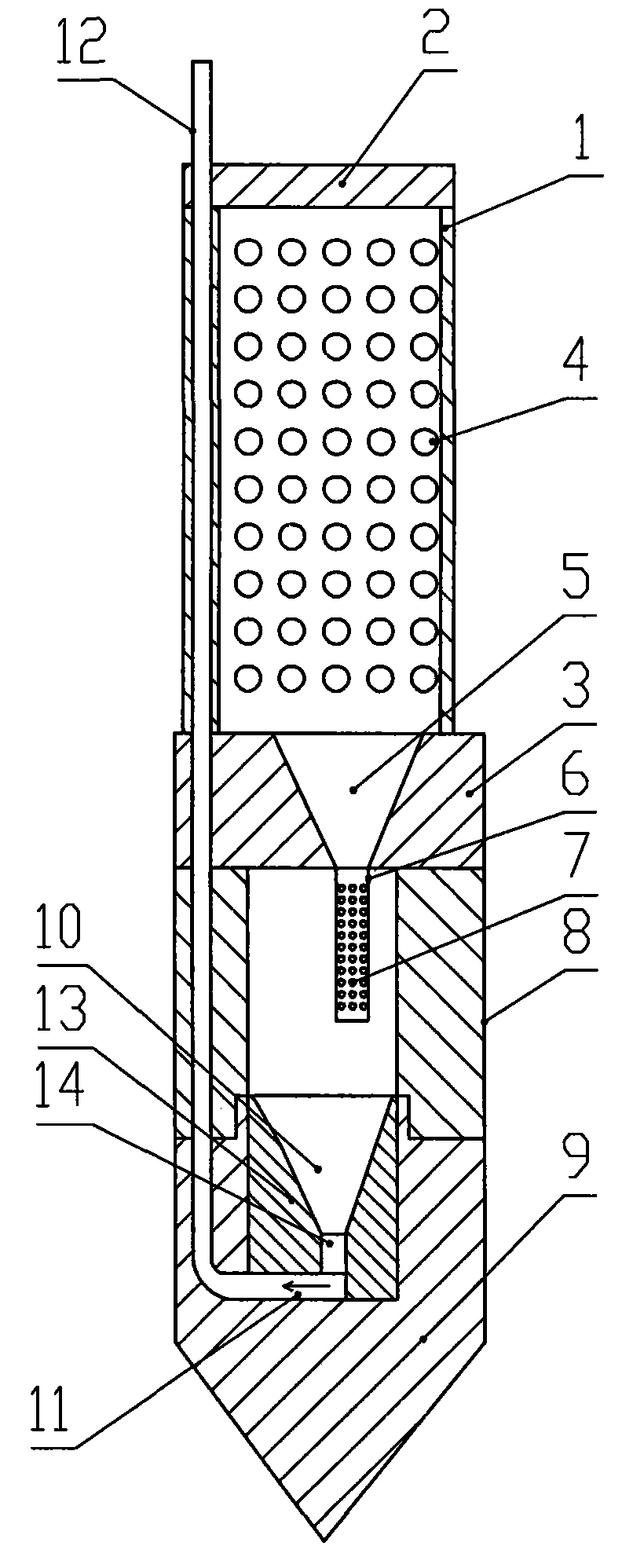
[0034] Such as image 3 As shown, the difference from the first embodiment is that the insect extraction pipe 12 passes through the side walls of the insect attracting rod 1 and the connecting rod 8 in sequence, the lower end of the insect extraction pipe 12 is bent to the right, and directly connects with the vertical pipe 14. The funnel 10 is connected. A bent section of pipeline forms the insect collecting space 11 instead of being formed by the insect collecting device 13 and the cone head 9 .

Embodiment approach 3

[0036] Such as Figure 4 As shown, the difference from Embodiment 1 is that the insect pumping tube 12 is arranged outside the insect trap rod 1, and no longer passes through the plug 2, the insect trap rod 1, the joint 3, the connecting rod 8 and the funnel 10, and finally Connect with Bug Space 11.


PUM


Abstract

The invention discloses a grain condition detecting rod which comprises a hollow insect attracting pipe and a conical head; the upper end of the insect attracting pipe is provided with a plug; the pipe wall of the insect attracting pipe is provided with an insect attracting opening; and an insect collecting device is provided between the insect attracting pipe and the conical head. the insect attracting pipe is connected with the conical head; the insect collecting device comprises an insect collector which is hollow at the upper part and is provided with a groove that forms an insect collecting space; the hollow part at the upper part of the insect collector is communicated with the insect collecting space; the insect collecting space is connected with an insect drawing pipe which penetrates the plug, the insect attracting pipe and the insect collector; and the lower end of the insect drawing pipe is communicated with the insect collecting space. As the grain condition detecting rod is provided with an insect collecting device, a negative pressure environment which facilitates the drawing is easily formed when the insect that comes into the insect collecting device is drawn thereby quickly drawing the insect out. An independent insect collecting space is provided in the insect collector, and the forming of drawing negative pressure environment is furthermore ensured, and therefore the non-stop and quick drawing-out of insect in drawing can be ensured.

Description

technical field [0001] The invention relates to a sampling device, in particular to a device for sampling pests or extracting gas inside a granary. Background technique [0002] During post-harvest storage of grain, stored grain pests do serious harm to grain and cause great economic losses. The traditional grain storage adopts the method of sampling and screening, which not only has a large workload, high labor intensity, and poor working environment, but also has low accuracy and lags behind in pest forecasting. For this reason, it is a topic of great concern in the field of stored grains to be able to predict early and detect the types, density and quantity of stored grain pests at any time. [0003] Existing detection is to insert in the middle of the grain with a detection rod, and the rod is provided with a plurality of small holes. After the insects climb into the rod, the rod is manually taken out, and then the types and quantities of the insects are analyzed and c...

Claims


Application Information

Patent Timeline
Patent Type & Authority Applications(China)
IPC IPC(8): G01N1/02G01N1/24A01M1/10
Inventor 姚海峰刘平安毛宝雨段晋曹阳段景智段宁
Owner ZHENGZHOU XINSHENG ELECTRONICS TECH
Learn More