Optical fiber cabling die

A cabling and optical fiber technology, applied in the direction of fiber mechanical structure, etc., can solve problems such as bare fiber processing, avoid damage or breakage, high assembly accuracy, and facilitate accurate threading and guidance.

Active Publication Date: 2010-02-24
河南仕佳通信科技有限公司
View PDF1 Cites 12 Cited by
  • Summary
  • Abstract
  • Description
  • Claims
  • Application Information

AI Technical Summary

Problems solved by technology

[0005] The purpose of the present invention is to provide an optical fiber cabling mold that utilizes bare optical fibers to process optical cables and at the same time adds re

Method used


Image

  • Optical fiber cabling die

Examples


Embodiment Construction

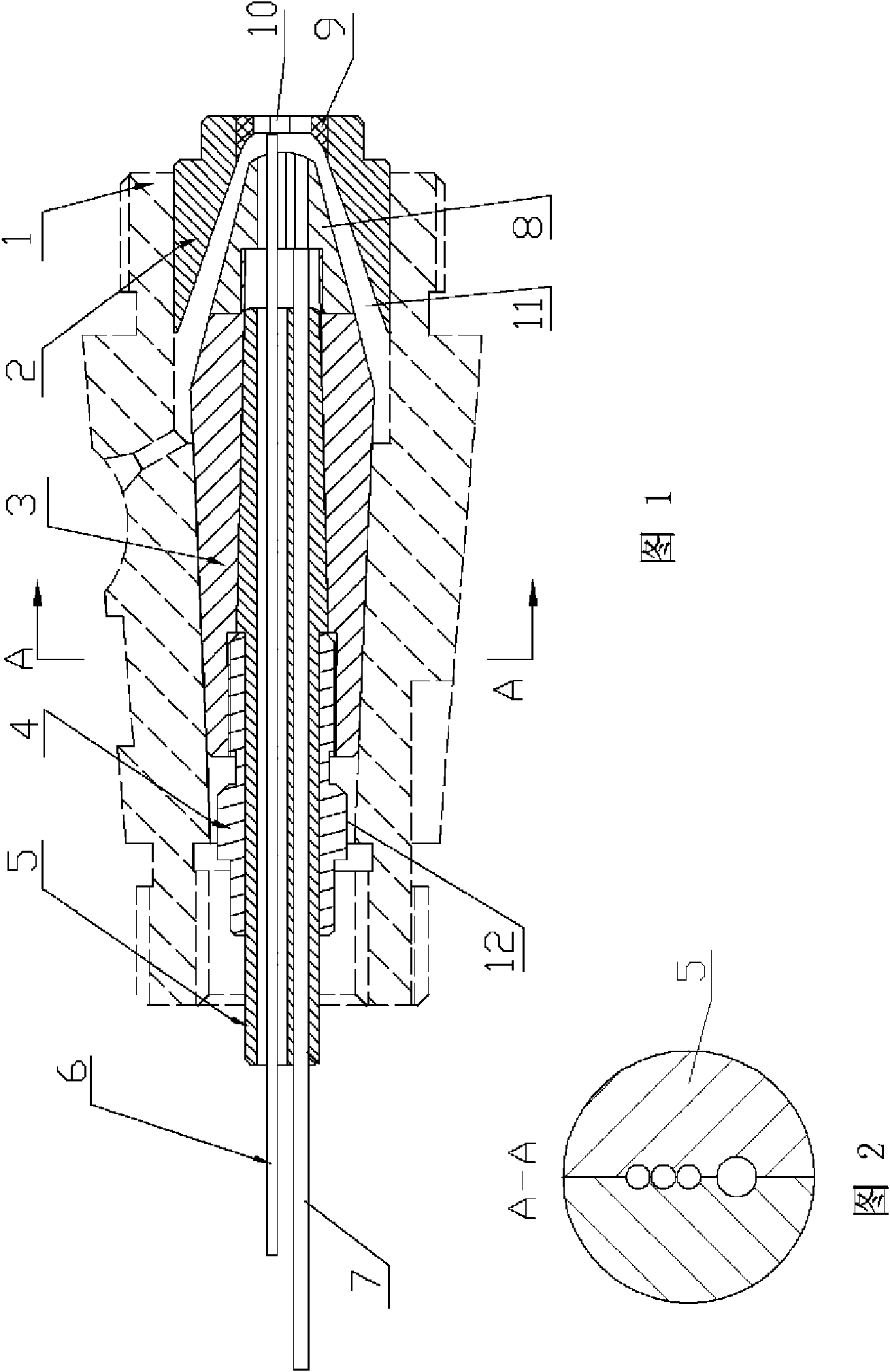
[0016] figure 1 , figure 2 The optical fiber cabling mold shown includes a mold sleeve and a mold core. The front end of the mold core is tapered, and the front end of the mold core cooperates with the mold sleeve with a tapered hole to form a tapered flow channel 11 . The mold cover 2 is composed of the main body of the mold cover and the sleeve body 9 coaxially embedded in the central through hole of the front end of the main body of the mold cover. The parts that are easy to block and easy to wear are set as independent detachable structures, which is convenient for maintenance and reduces maintenance costs.

[0017] The mold core 3 is composed of a core head 8 and a core body. The core body and the core head 8 are screwed into one body, so that the mold core forms a detachable split connection structure. The center of the mold core 3 has an axial taper hole, the front end of the axial taper hole runs through the front end of the mold core, and the tail end of the axial ...


PUM


Abstract

The invention relates to an optical fiber cabling die which comprises a die sleeve and a die core. A die core plug-in is inserted in an axial conical hole in the center of the die core and internallyand axially provided with at least one optical fiber channel and at least one reinforcer channel; an optical fiber guiding protective tube is fixedly mounted in each optical fiber channel; the die sleeve is provided with a conical hole; the front end of the die core is in a conical shape and is matched with the conical hole of the die sleeve to form a conical flow passage which is communicated with the reinforcer channels; the front end of die core plug-in is arranged in the die core; each optical fiber guiding protective tube penetrates through both ends of the die core plug-in; and the frontend of each optical fiber guiding protective tube extends forwards to a position between an inner port and an outer port of an extrusion hole of the die sleeve. The optical fiber cabling die processes a bare optical fiber into an optical fiber and enables melted plastics to not only tightly wrap the reinforcer, but also avoid damaging the bare optical fiber in a cabling process, thereby ensuringthe quality of the processed optical fiber.

Description

technical field [0001] The invention relates to an optical fiber cable forming mold. Background technique [0002] At present, the molds used in the production of optical cables generally include extrusion molds and extrusion molds. Extrusion molds such as figure 1 As shown, the mold core 2 and the mold sleeve 1 are separated by a suitable gap, and the molten plastic flows through the conical flow channel formed by the two, and has been in contact with the cable core before the mold is ejected; Horizontally, a great pressure is formed in the direction of the vertical cable core, and this pressure can wrap the cable core tightly. extruded tube die figure 2 As shown, the front end of the mold core 4 has a fixed-length sleeve bearing diameter 5, and the bearing diameter part is inserted into the inner hole of the mold sleeve 3, and is flush with the front end of the mold sleeve 3; The mold is ejected, and the molten plastic is ejected from the annular flow channel between t...

Claims


Application Information

Patent Timeline
IPC IPC(8): G02B6/44
Inventor 崔卫星陈荣顺李然山
Owner 河南仕佳通信科技有限公司
Why Eureka
Try Eureka