Sifting device

A filter device and filter rod technology, which is applied in the direction of filter separation, filter screen, fixed filter element filter, etc., can solve the problem of inaccurate geometry of filter slits, inaccurate relative attachment, dispersion of filter slit or gap width, etc. problem, to achieve reliable and precise orientation, and permanent connection, reliable connection

Active Publication Date: 2010-02-24
ANDRITZ FIEDLER
View PDF4 Cites 5 Cited by
  • Summary
  • Abstract
  • Description
  • Claims
  • Application Information

AI Technical Summary

Problems solved by technology

The use of welding or brazing processes may create additional difficulties, since the relative attachment of the filter rod to the receiving cutout in the support is imprecise due to the high temperatures used in these processes and the resulting different thermal expansion properties. , these factors can cause undesired width dispersion of filter slits or gaps and corresponding inaccuracies in the geometry of the filter slits

Method used


Image

  • Sifting device
  • Sifting device
  • Sifting device

Examples


Embodiment Construction

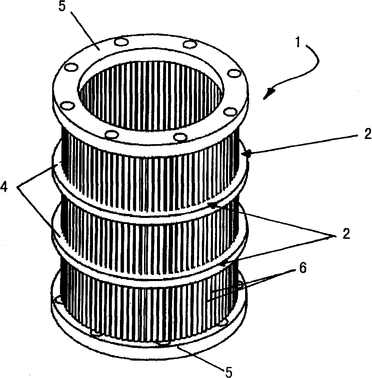
[0026] figure 1 A cylindrical filter basket 2 is shown representing a preferred exemplary embodiment of a filter device, which is generally designated with reference numeral 1 . It will be appreciated that the filter device 1 of the present invention can also be constructed as a filter plate. Said filter device 1 comprises supports 3 , which in the illustrative example are formed as support rings 4 . Furthermore, so-called end flanges 5 are provided in the axial end regions of the filter device 1 . Inserting the filter rod 6 into the corresponding receiving cutout of the support 3 forms a corresponding filter slit or filter gap between the head regions of the filter rod 6 . exist figure 1 Such rod filter baskets are schematically shown in and are known in the art.

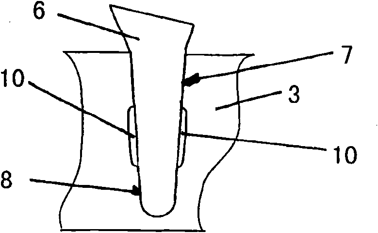
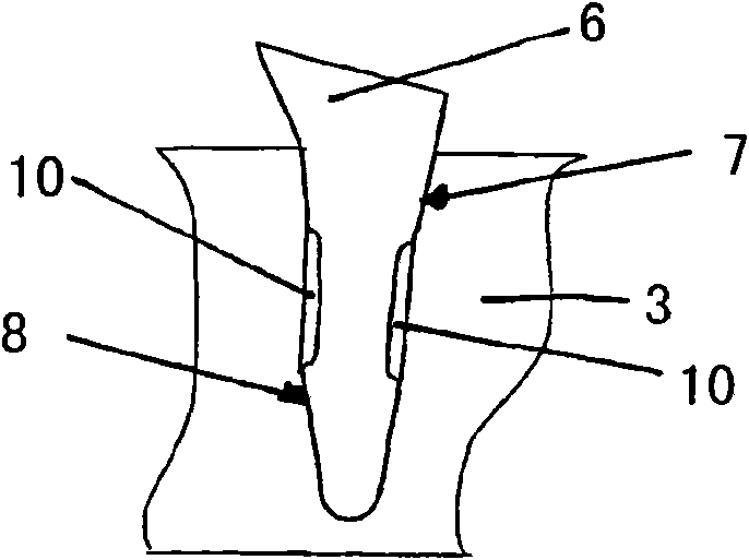
[0027] as by Figures 1 to 10 As can be seen, the filter device according to the invention is designed with pockets 10 located between each support 3 and each associated filter rod 6, at least on the supports ...


PUM

PropertyMeasurementUnit
sizeaaaaaaaaaa
heightaaaaaaaaaa

Abstract

The invention relates to a sifting device, such as a perforated basket, a perforated cylinder or the like, in which slits or gaps are formed between sieve bars (6). The base of the sieve bars is received in receiving recesses (8) adapted to the dimensions of the base of the bars, in a carrier element (3). Said carrier element can also be a reinforcing or strengthening element, and the sieve bars (6) are permanently fixed to the respective carrier element (3). At least one pocket (10, 11) that can be filled with a filler material is provided between each carrier element (3) and each associated sieve bar (6), at least on the edge region (7) of the respective receiving recess (8). In the sifting device according to the invention, said pocket interrupts the contact surface between the outer contour of the sieve bar (6) and the inner contour of the associated receiving recess in the carrier element (3), such that a pre-determined intermediate space is formed in a targeted manner in the form of a pocket (10; 11), at least on the edge region (7). Said pocket is then filled with a homogeneous or composite filler material used as a fixing means, a constituent of said filler material being, for example, an adhesive. In this way, a permanent solid connection can be created between sieve bars (6) and carrier elements (3).

Description

technical field [0001] The present invention relates to a filter device (or filter device) in which filter slits or filter gaps are formed between preferably profiled strainer bars, the filter rods having base areas which are accommodated in the receiving cutouts of the supports and the filter rods are permanently mounted to these supports. These filter units are also referred to as "rod filter units". These filter devices can be formed as flat screen panels or as circular strainer baskets. Background technique [0002] Filtering devices employing this so-called "rod screen configuration" are known in the art. For example, patent document EP 0316570 describes a filter basket and a method of producing such a filter basket having filter slits extending parallel to its axis of rotational symmetry and comprising individual profile bars Alternatively, the filter rods are formed, inserted into previously milled cutouts, and these cutouts are located on supports made into suppor...

Claims


Application Information

Patent Timeline
Patent Type & Authority Applications(China)
IPC IPC(8): B07B1/46B07B1/12B01D29/44B01D33/073
CPCB01D29/445B01D33/073B07B1/12B07B1/4618D21D5/16
Inventor T·麦克拉特C·蒂奇
Owner ANDRITZ FIEDLER
Why Eureka
Try Eureka