Optical member manufacturing method, optical member manufacturing apparatus and optical member

A technology for optical components and nano-composite materials, which is applied in the field of forming optical components from nano-composite materials, can solve the problems of poor fluidity, difficult to form products, and cannot obtain resin fluidity, etc., and achieves the effect of stabilizing optical properties and improving processing performance.

Inactive Publication Date: 2010-02-24
FUJIFILM CORP
View PDF5 Cites 3 Cited by
  • Summary
  • Abstract
  • Description
  • Claims
  • Application Information

AI Technical Summary

Problems solved by technology

In particular, in order to increase the refractive index, it is necessary to disperse a large number of fine particles, so that the fluidity becomes worse
[0013] Therefore, when injection molding nanocomposite resins, resin fluidity required for injection molding cannot be obtained even at high temperatures, making it difficult to mold good products

Method used


Image

  • Optical member manufacturing method, optical member manufacturing apparatus and optical member
  • Optical member manufacturing method, optical member manufacturing apparatus and optical member
  • Optical member manufacturing method, optical member manufacturing apparatus and optical member

Examples


no. 1 approach

[0086] First, a first embodiment of the optical element manufacturing method according to the present invention will be described.

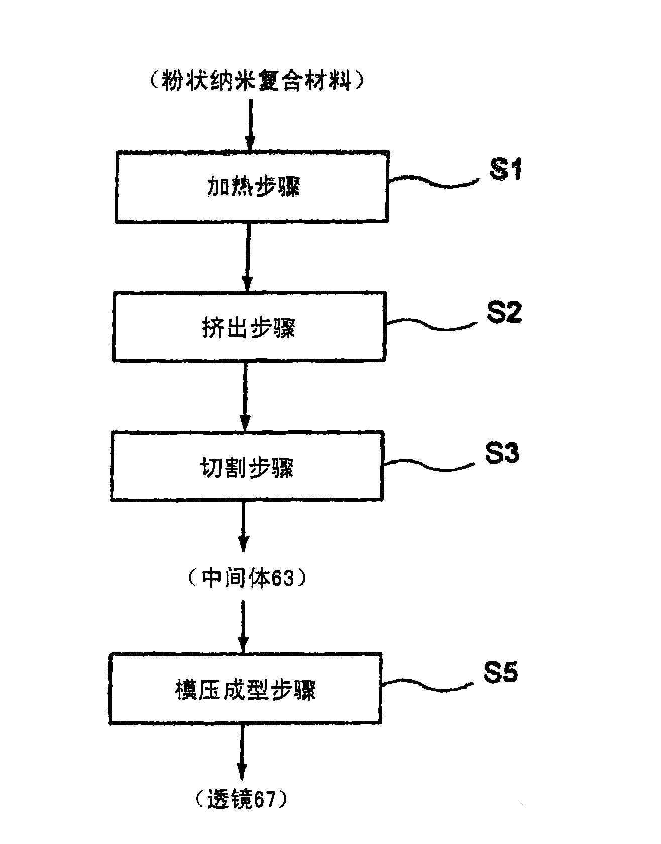
[0087] figure 1 The flow chart of is showing a schematic procedure of the optical element manufacturing method according to the first embodiment of the present invention.

[0088] Such as figure 1 As shown, the nanocomposite powder passes through an intermediate forming device to be described later to form a bulk intermediate 63 through a heating step (step 1: S1), an extrusion step (S2) and a cutting step (S3). Then, the intermediate body 63 is heated (S4) and compressed by press molding, thereby manufacturing an optical element 67 such as a lens. The nanocomposite powder is a material in which inorganic fine particles each having an average particle diameter of 1 to 15 nm are dispersed in a thermoplastic resin, the details of which will be described later.

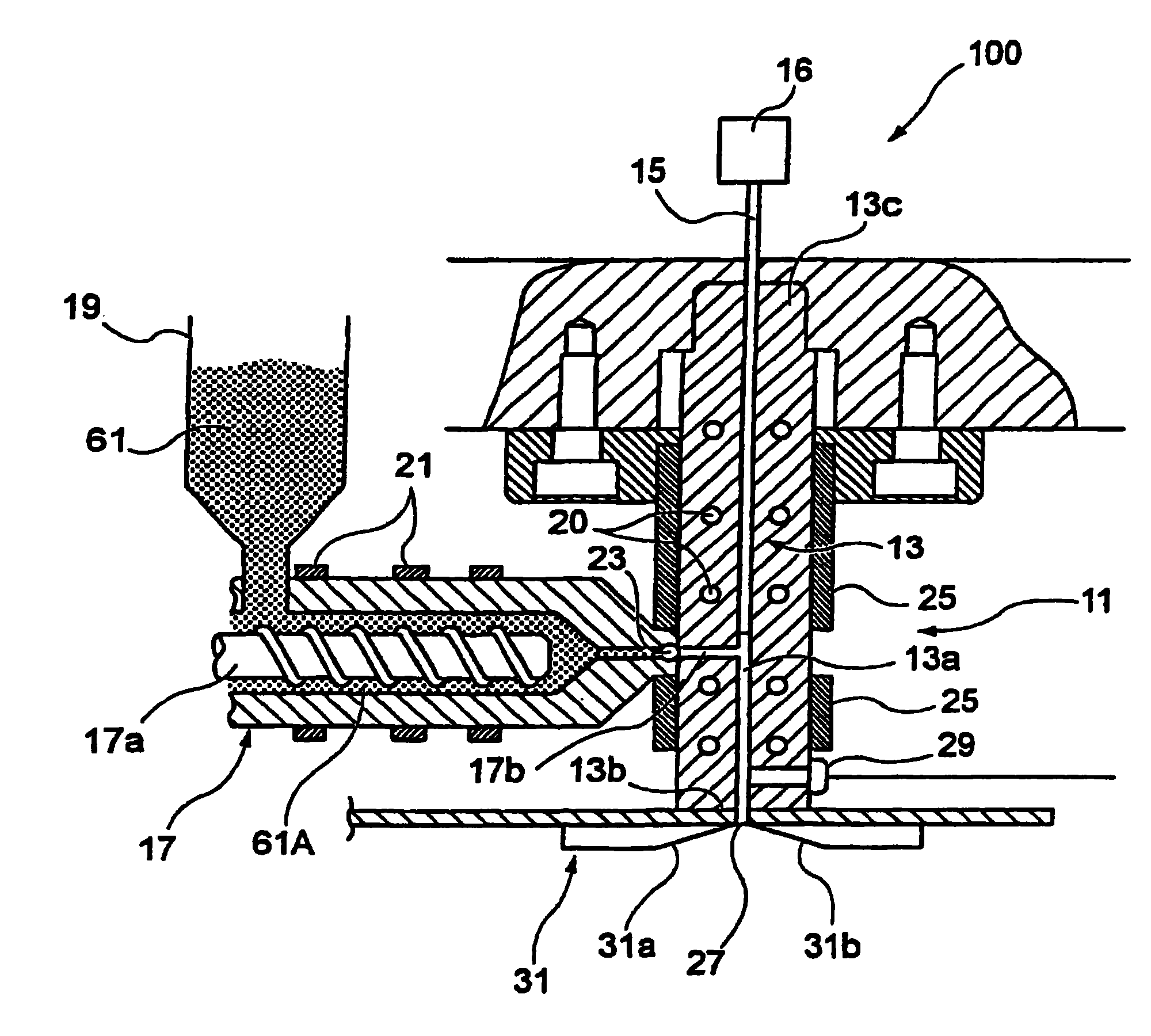
[0089] The above steps are described in order below. First, through figure 2 The ...

no. 2 approach

[0121] The following will refer to Figures 6 to 8 A second embodiment of the optical element manufacturing method according to the present invention is described.

[0122] Figure 6 The flowchart of shows the schematic procedure of the optical element manufacturing method according to the second embodiment of the present invention, Figure 7 An illustrative view showing the steps of forming a preform by thermally compressing a bulk intermediate, Figure 8 The illustrative view of shows the steps of forming an optical element from a preform by compression molding equipment (compression molding equipment).

[0123] Such as Figure 6 As shown, in the optical element manufacturing method of this embodiment, a bulk intermediate is formed through the heating step (S1), extrusion step (S2) and cutting step (S3) similar to those of the first embodiment. Then, the intermediate body is compressed in a compression step S5, thereby molding into a preform having a shape close to that ...

no. 3 approach

[0131] The following will refer to Figure 9 and Figure 10 A third embodiment of the optical element manufacturing method according to the present invention is described.

[0132] Figure 9 A flowchart showing a schematic procedure of the optical element manufacturing method in the third embodiment, Figure 10 An illustrative view showing the steps of forming a preform directly from the nanocomposite powder by thermally compressing the nanocomposite powder.

[0133] In the schematic manufacturing method of the optical element of this embodiment, as Figure 9 As shown, the nanocomposite powder is put into the preform forming device as it is, and is formed into a preform whose shape is close to that of a lens (optical element) through a heating step (S7) and a compression step (S8). Then, in a compression molding step (S9) similar to that in the second embodiment, a final product optical element is produced. This embodiment differs from the second embodiment in the preform...


PUM

PropertyMeasurementUnit
particle sizeaaaaaaaaaa
glass transition temperatureaaaaaaaaaa

Abstract

A method for manufacturing an optical member from a powdery nano composite material, which includes a thermoplastic resin containing inorganic fine particles, is provided. The method includes: preparing an aggregated intermediate body by heating the powdery nano composite material; and forming the optical member having a finished shape by heat-press molding the intermediate body.

Description

technical field [0001] The present invention relates to an optical element manufacturing method, an optical element manufacturing apparatus, and an optical element; in particular, the present invention relates to a technique for forming an optical element using a nanocomposite material. Background technique [0002] With the recent improvement in performance, miniaturization and cost reduction of optical information recording devices such as portable cameras, DVD, CD, and MO drives, optical elements (such as optical lenses or filters) used in these optical information recording devices are in great demand for excellent material and method development. [0003] In particular, plastic lenses are lighter and harder to break than inorganic materials such as glass, can be processed into various shapes, and can be produced at low cost. Therefore, the application of plastic lenses is rapidly expanding not only to glass lenses but also to the aforementioned optical lenses. With su...

Claims


Application Information

Patent Timeline
Patent Type & Authority Applications(China)
IPC IPC(8): B29D11/00B29C43/34B29C69/02B29C47/92B29C48/92
CPCB29C31/048B29D11/00432B29C43/34B29C2043/3433B29C47/004B29C2043/3618B29L2011/0016B29C43/361B29C2043/503B29C47/0016B29C2043/5007B29K2303/06B29C47/0019B29K2503/04B29C2043/5808B29C47/0066B29C47/54B29K2105/162B29C2793/0027B29K2105/16B29C47/20B29C48/0011B29C48/0022B29C48/06B29C48/07B29C48/388B29C48/475B29C48/9185B29C48/92B29C2948/92019B29C2948/92142B29C2948/92428B29C2948/92438B29C2948/92514B29C2948/92609B29C2948/92638B29C2948/92704B29C2948/92895B29C2948/92923B29C2948/92933B29C69/02B29D11/00
Inventor 荣羽范子渡边清一吉冈将人
Owner FUJIFILM CORP
Why Eureka
Try Eureka