
Optical chip for arrayed waveguide grating type optical multiplexer/demultiplexer circuit, waveguide substrate, and method for fabricating optical chip for arrayed waveguide grating type optical multiplexer/demultiplexer circuit

a technology of arrayed waveguides and optical multiplexers, applied in the field of optical chips, can solve the problems of stability of optical characteristics and the yield rate of optical chips, and achieve the effects of stable optical characteristics, high yield rate, and hardly deformation

Active Publication Date: 2012-02-07
NTT ELECTORNICS CORP
View PDF7 Cites 2 Cited by
  • Summary
  • Abstract
  • Description
  • Claims
  • Application Information

AI Technical Summary

Benefits of technology

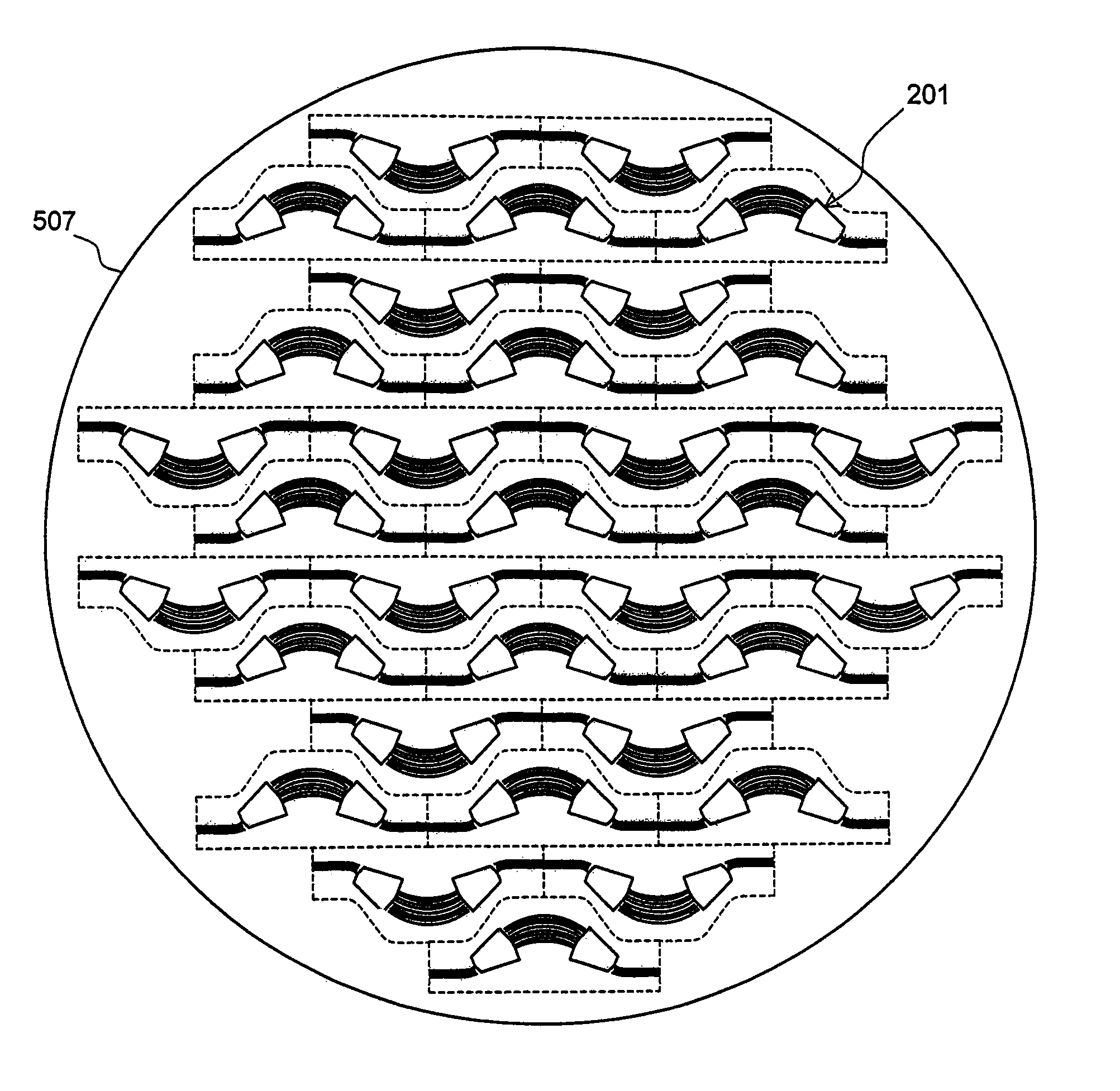
This design enhances the optical chip yield rate and stabilizes optical characteristics by distributing physical stress evenly, allowing for more efficient chip arrangement and improved multiplexer / demultiplexer performance without additional reinforcement, thus reducing the unit price and increasing the number of functional chips per substrate.

Problems solved by technology

As a consequence, the optical chip for the conventional arrayed waveguide grating type optical multiplexer / demultiplexer circuit has involved a problem of the optical chip yield rate in the case of the rectangular shape whereas a problem of the stability of the optical characteristics in the case of the arcuate shape.

Method used


Image

  • Optical chip for arrayed waveguide grating type optical multiplexer/demultiplexer circuit, waveguide substrate, and method for fabricating optical chip for arrayed waveguide grating type optical multiplexer/demultiplexer circuit
  • Optical chip for arrayed waveguide grating type optical multiplexer/demultiplexer circuit, waveguide substrate, and method for fabricating optical chip for arrayed waveguide grating type optical multiplexer/demultiplexer circuit
  • Optical chip for arrayed waveguide grating type optical multiplexer/demultiplexer circuit, waveguide substrate, and method for fabricating optical chip for arrayed waveguide grating type optical multiplexer/demultiplexer circuit

Examples


Embodiment Construction

[0038]Embodiments according to the present invention will be described in reference to the attached drawings. The embodiments described below exemplify the present invention, which, therefore, is not limited to the following embodiments.

(Optical Chip for Arrayed Waveguide Grating Type Optical Multiplexer / Demultiplexer Circuit)

[0039]The present embodiment is directed to an optical chip for an arrayed waveguide grating type optical multiplexer / demultiplexer circuit including two slab waveguides, an array waveguide for connecting the slab waveguides via a plurality of channel waveguides different in optical path length and curved in one direction, and at least one or more input / output waveguides connected to the slab waveguides, respectively, on sides opposite to the array waveguide, wherein one edge is formed into a shape projecting outward of a curve of the array waveguide by connecting a first line of two fold rotational symmetry and a second line of two fold rotational symmetry whe...


PUM


Abstract

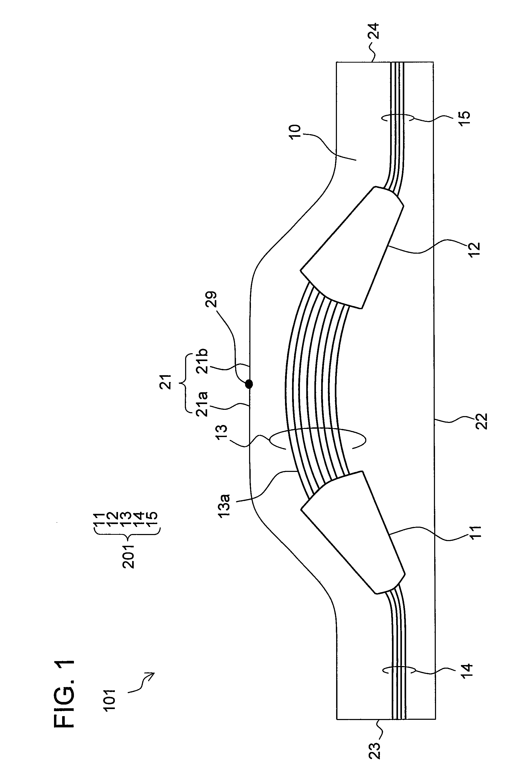
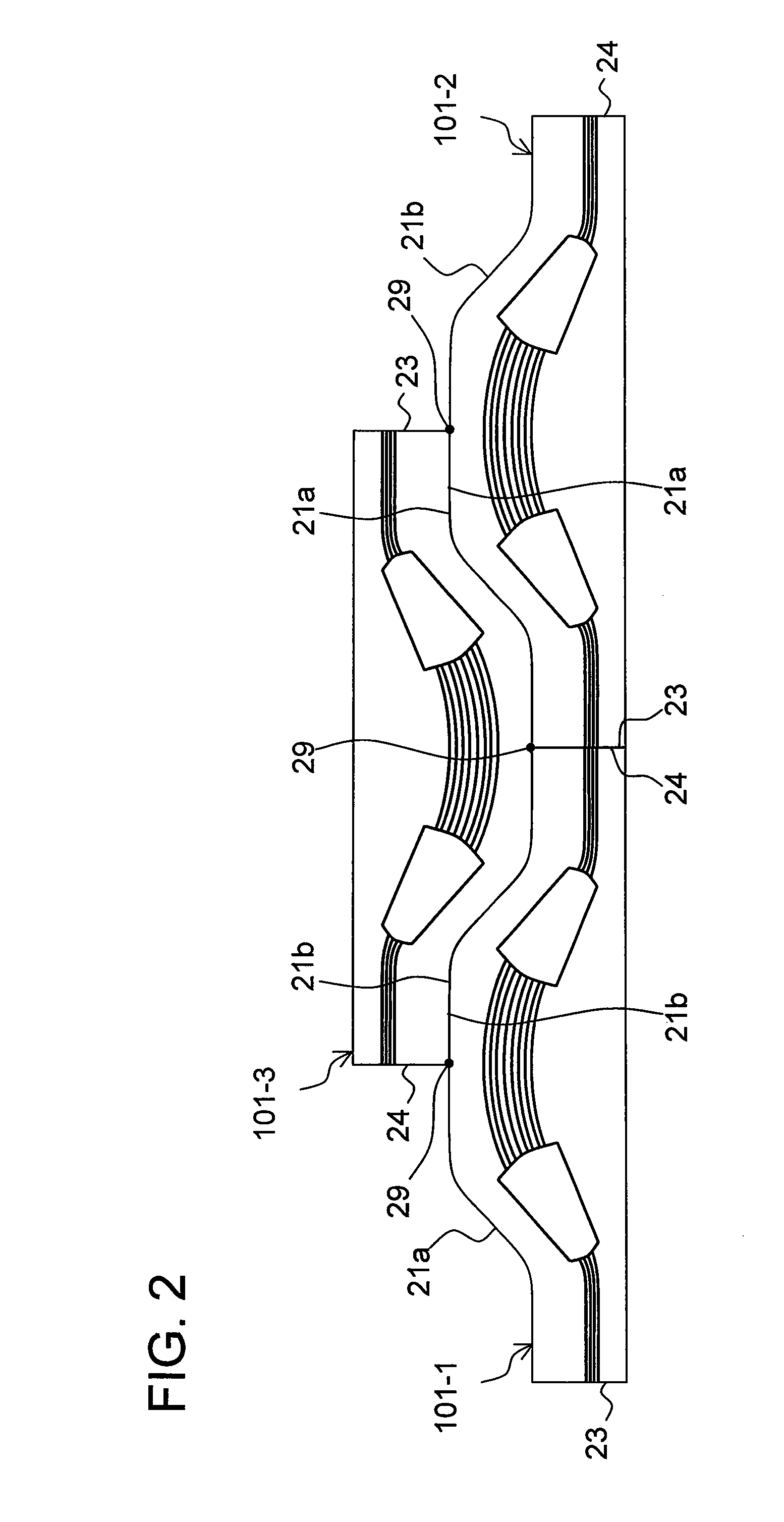
An optical chip according to the present invention is formed into a projecting shape expanded toward either side at the center. A waveguide substrate has a layout in which arrayed waveguide grating type optical multiplexer / demultiplexer circuits, each having a curve direction of an array waveguide reverse to each other, are arranged in combination, and the optical chips are cut out of the waveguide substrate. A method for fabricating the optical chip according to the present invention can enhance an optical chip yield rate, and further, can fabricate an optical chip having the shape for stabilizing optical characteristics of the arrayed waveguide grating type optical multiplexer / demultiplexer circuit.

Description

CROSS REFERENCE TO RELATED APPLICATION[0001]This is a U.S. national phase application under 35 U.S.C. §371 of International Patent Application No. PCT / JP2007 / 066851 filed Aug. 30, 2007 and claims the benefit of Japanese Application No. JP2006-247695, filed Sep. 13, 2006. The International Application was published on Mar. 20, 2008 as International Publication No. WO / 2008 / 032579 under PCT Article 21(2) the content of both applications are incorporated herein in their entirety.TECHNICAL FIELD[0002]The present invention relates to an optical chip including an arrayed waveguide grating type optical multiplexer / demultiplexer circuit, a waveguide substrate having a plurality of patterns for an arrayed waveguide grating type optical multiplexer / demultiplexer circuit formed thereon, and a method for fabricating an optical chip including an arrayed waveguide grating type optical multiplexer / demultiplexer circuit.BACKGROUND OF THE INVENTION[0003]An arrayed waveguide grating type optical multi...

Claims


Application Information

Patent Timeline
Patent Type & Authority Patents(United States)
IPC IPC(8): G02B6/12
CPCG02B6/12021G02B6/13
Inventor KUWANO, SHUJIMORIYA, YUJIMASUDA, TAKAMITSU
Owner NTT ELECTORNICS CORP
Learn More