

Display module, display device, and liquid crystal television set
a technology of display device and display module, which is applied in the direction of television system, lighting and heating apparatus, instruments, etc., can solve the disadvantages of unstable optical characteristics of backlight emitted from light guide plate, and achieve the effect of stabilizing the optical characteristics of backlight and reducing the amount of change in a clearan
- Summary
- Abstract
- Description
- Claims
- Application Information
AI Technical Summary
Benefits of technology
Problems solved by technology
Method used
Image

Examples
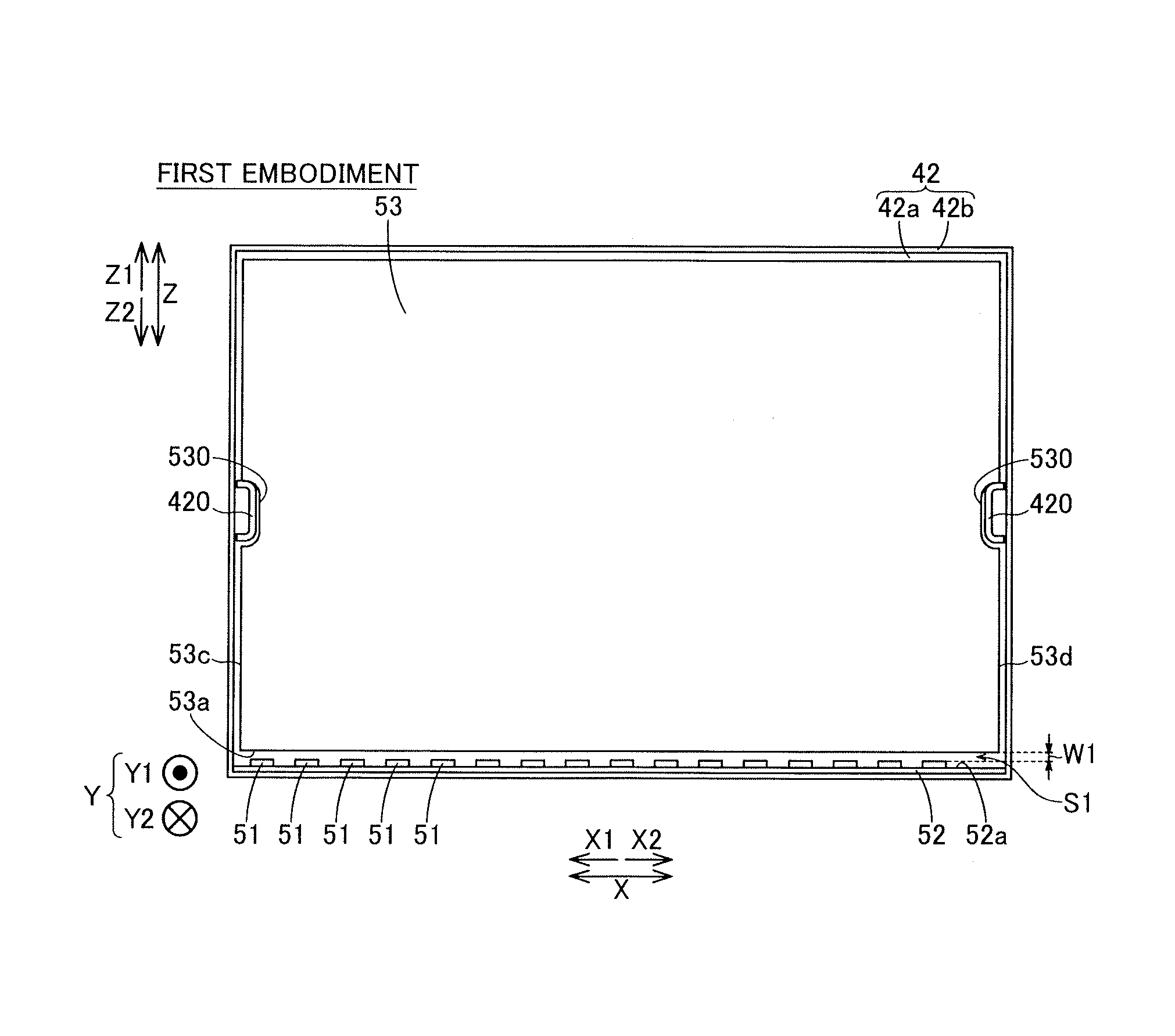
first embodiment
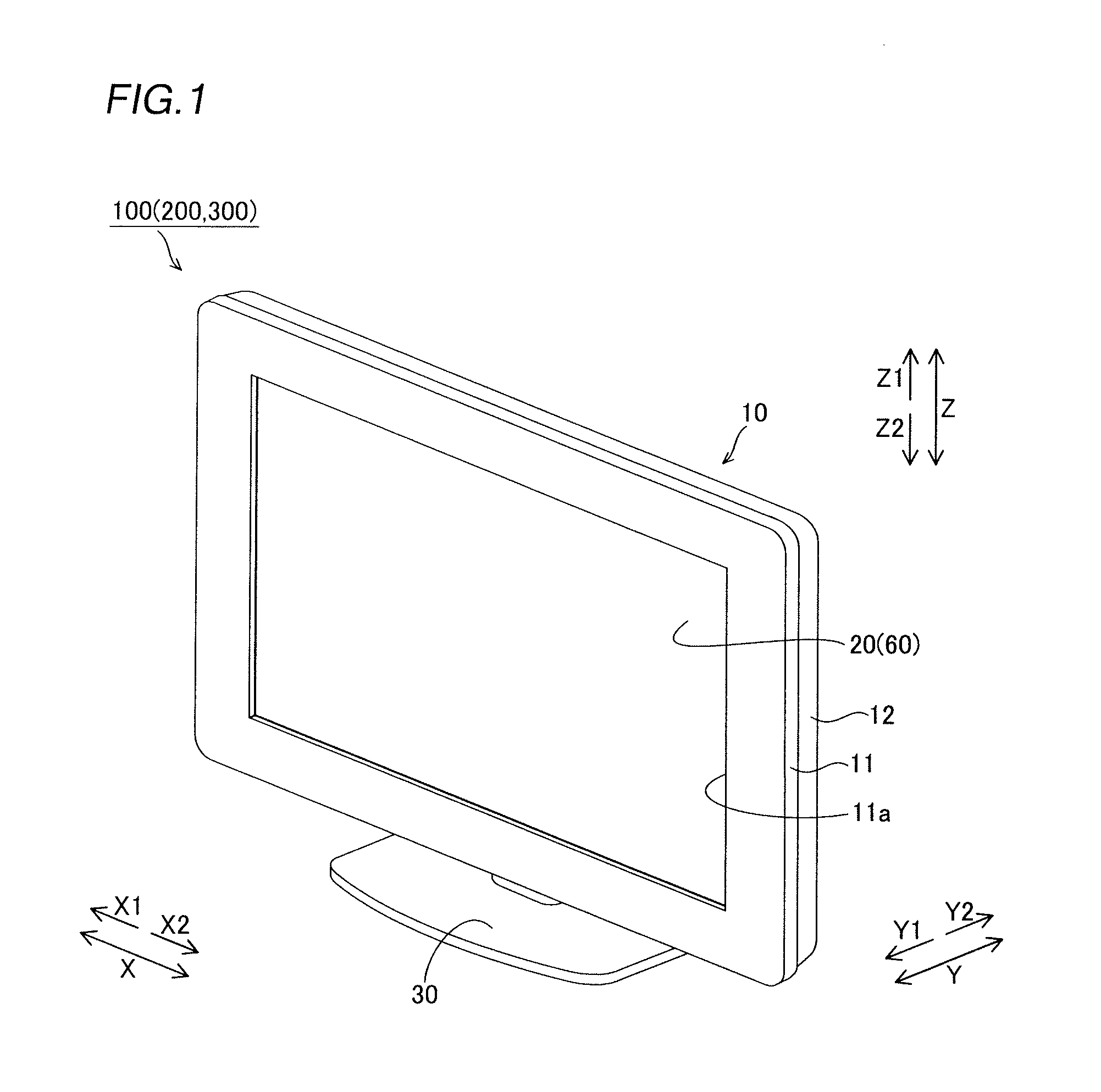
[0045]First, the structure of a liquid crystal television 100 according to a first embodiment of the present invention is described with reference to FIGS. 1 to 7. The liquid crystal television 100 is an example of the “display device” or the “liquid crystal television set” in the present invention.
[0046]The liquid crystal television 100 according to the first embodiment of the present invention includes a television body 10 having a display portion 20 displaying an image and a stand member 30 supporting the television body 10 from below (along arrow Z1), as shown in FIG. 1.
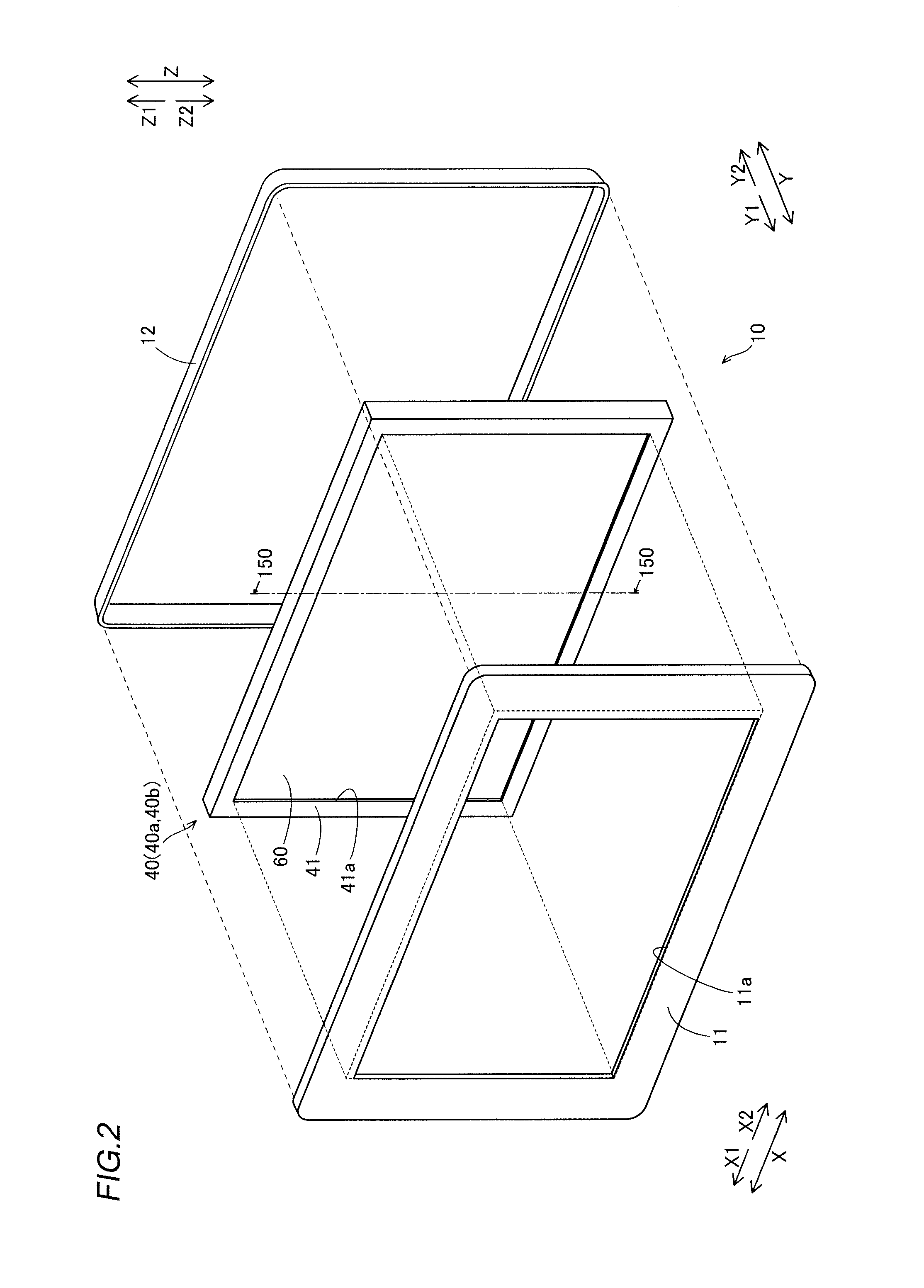
[0047]As shown in FIGS. 1 and 2, the television body 10 includes a front cabinet 11 and a rear cabinet 12 each made of resin and a liquid crystal display module 40 having a liquid crystal display cell 60 constituting the display portion 20. The front cabinet 11 and the rear cabinet 12 are examples of the “housing” in the present invention while the same are examples of the “television housing” in the present inve...
second embodiment
[0080]First, the structure of a liquid crystal television 200 according to a second embodiment of the present invention is described with reference to FIGS. 1 to 4, 8 and 9. The liquid crystal television 200 is an example of the “display device” or the “liquid crystal television set” in the present invention. In this second embodiment, portions (see FIG. 8) coming into contact with each other when a light guide plate 56 and a rear frame 44 engage with each other include portions (inclined portions 561 and 441) inclined by a prescribed angle θ1 with respect to a mounting surface 52a dissimilarly to the aforementioned first embodiment in which the portions (see FIG. 6) coming into contact with each other when the light guide plate 53 and the rear frame 42 engage with each other include the portions (parallel portions 531 and 421) parallel to the mounting surface 52a of the glass epoxy board 52 and the arcuate portions (532 and 422).
[0081]The liquid crystal television 200 according to ...
third embodiment
[0097]First, the structure of a liquid crystal television 300 according to a third embodiment of the present invention is described with reference to FIGS. 1 to 4, 10 and 11. The liquid crystal television 300 is an example of the “display device” or the “liquid crystal television set” in the present invention. In this third embodiment, portions (see FIG. 10) coming into contact with each other when a light guide plate 57 and a rear frame 45 engage with each other include portions (inclined portions 571 and 451) inclined by a prescribed angle θ2 with respect to a mounting surface 52a and portions (parallel portions 572 and 452) parallel to the mounting surface 52a dissimilarly to the aforementioned second embodiment in which the portions (see FIG. 8) coming into contact with each other when the light guide plate 56 and the rear frame 44 engage with each other include only the portions (inclined portions 561 and 441) inclined by the prescribed angle θ1 with respect to the mounting sur...
PUM
 Abstract
Description
Claims
Application Information