Vane type vacuum pump

一种真空泵、叶片式的技术,应用在旋转活塞式泵、泵、泵元件等方向,能够解决单向阀破损、压力变高、叶片破损等问题

Inactive Publication Date: 2010-02-24
TAIHO INDUSTRIES CO LTD
View PDF1 Cites 7 Cited by
  • Summary
  • Abstract
  • Description
  • Claims
  • Application Information

AI Technical Summary

Problems solved by technology

If the blades are reversed in this state, if the above-mentioned relief groove is not provided, since the lubricating oil is an incompressible fluid, the pressure near the suction passage will be abnormally high, and the blades will be damaged, or the blades will be damaged. When the check valve that allows air flow to the pump chamber is installed in the middle of the suction passage, there is a problem that the check valve is damaged

Method used


Image

  • Vane type vacuum pump
  • Vane type vacuum pump
  • Vane type vacuum pump

Examples


Embodiment Construction

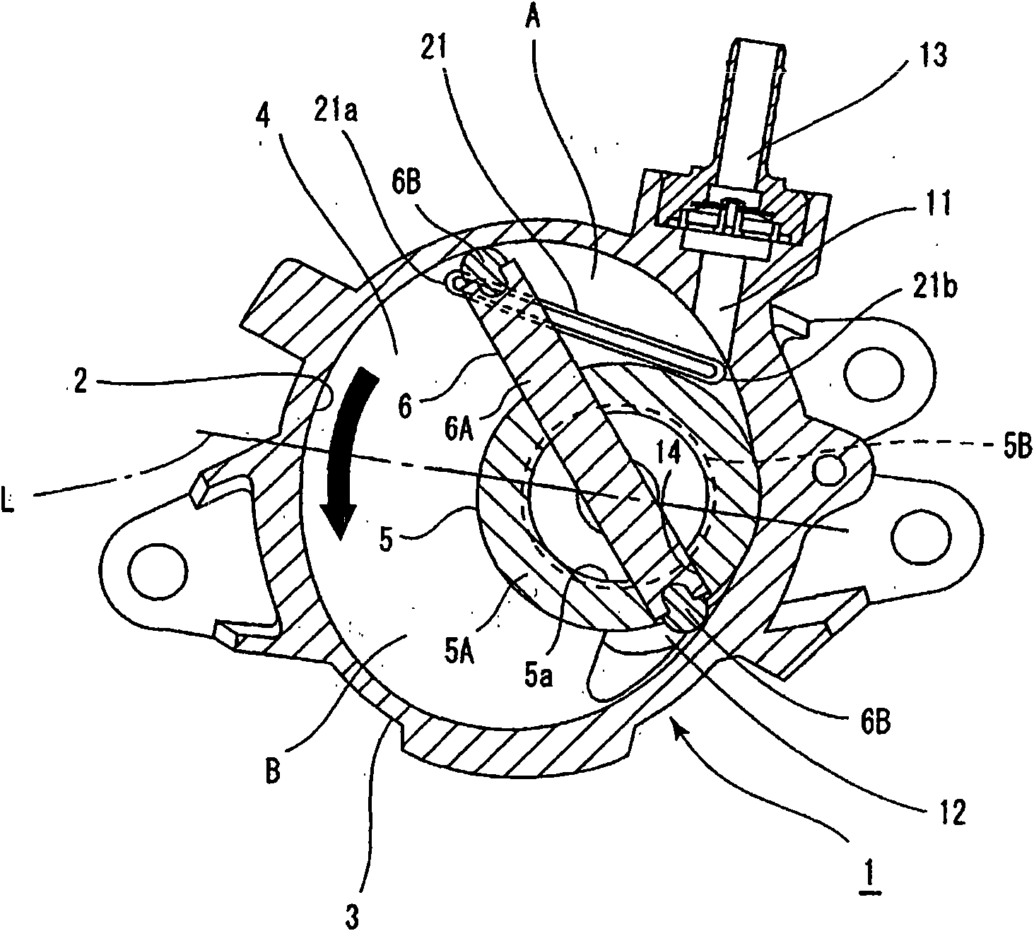
[0006] The invention is illustrated below by way of illustrative examples. exist figure 1 Among them, the vane vacuum pump 1 is fixed on the side of the engine of the motor vehicle not shown in the figure, and the booster device of the brake device not shown in the figure generates negative pressure.

The vane vacuum pump 1 has a housing 3, a side plate 4 (only one side plate is shown in the figure), a rotor 5, and a vane 6; the housing 3 forms a substantially circular pump chamber 2; the side plate 4 seals the Both end surfaces of the casing 3; the rotor 5 is rotated by the driving force of the engine at a position eccentric with respect to the center of the pump chamber 2; the blade 6 is rotated by the above-mentioned rotor 5, and often divides the pump chamber 2 into a plurality of spaces; the above-mentioned rotor 5 and the blade 6 are rotationally driven in the counterclockwise direction indicated by the arrow in a normal state.

[0007] In the above-mentioned case 3, a...


PUM


Abstract

A vane type vacuum pump (1) is provided in the vicinity of a suction passage (11) for sucking air into a pump chamber (2), and has an escape groove (21) for communicating the space A on the front sideand the space B on the rear side in the rotational direction of a vane (6) during reverse rotation thereof to allow lubricant to escape from the space A on the front side to the space B on the rear side. The escape groove (21) is provided in a side plate (4), and the wall surface (21A) of the escape groove becoming the rear side in the rotational direction of the vane (6) during reverse rotationthereof is a slope enlarged on the opening side as compared with the bottom surface (21B) of the escape groove. Preferably, the other wall surface (21C) of the escape groove is also a slope enlarged on the opening side as compared with the bottom surface. As compared with a case where the escape groove (21) has a square cross-section, foreign matter and abrasion powder (22) are allowed to escape from the escape groove (21) smoothly.

Description

technical field [0001] The present invention relates to a vane type vacuum pump, and more particularly, to a vane type vacuum pump having a drain groove for releasing lubricating oil from a space on the front side of the vane to a space on the rear side when the vane is reversed. Background technique [0002] Conventionally, a vane vacuum pump provided with a drain groove for draining lubricating oil when the vanes are reversed is known (Patent Document 1). That is, the above-mentioned vane vacuum pump has a housing, side plates, rotors, vanes, and discharge grooves; the housing is provided with a substantially circular pump chamber; the side plates seal both ends of the housing; The center of the pump chamber rotates at an eccentric position; the vane reciprocates along a groove formed in the radial direction of the rotor, and rotates while dividing the pump chamber into a plurality of spaces; In the vicinity of the air intake passage, the space on the front side and the ...

Claims


Application Information

Patent Timeline
Patent Type & Authority Applications(China)
IPC IPC(8): F04C18/344F04C25/02F04C29/02
CPCF04C28/28F04C29/028F04C18/3441F04C18/344F04C25/02F04C29/02
Inventor 太田原清隆林田喜久治野口直人
Owner TAIHO INDUSTRIES CO LTD
Why Eureka
Try Eureka