Feeding device in steel processing device

A technology for processing equipment and steel, applied in the field of machinery, can solve the problems such as the inability of the roller shaft to work continuously, the low utilization rate of the roller table, and the low processing efficiency, and achieve the effect of saving operation time, improving processing efficiency and sufficient operation time.

Inactive Publication Date: 2010-03-03
刘传玲
View PDF0 Cites 5 Cited by
  • Summary
  • Abstract
  • Description
  • Claims
  • Application Information

AI Technical Summary

Problems solved by technology

[0004] However, every time steel is placed, the shot blasting machine must be turned off so that the rollers will not roll, and then the steel pipes to be processed are placed between the spacer bars on the rollers, and then the shot blasting machine is turned on to drive the rollers to rotate. The steel to be processed enters the shot blasting chamber, which is time-consuming and labor-intensive, and the utilization rate of the roller table is low, and the processing efficiency is not high
The processed steel still needs workers to carry and unload the material, which is time-consuming and labor-intensive
[0005] Other steel processing equipment conveyed by rollers also need to stop the rotation of the rollers when loading materials, and then rotate the rollers after loading the materials, so that the rollers cannot work continuously and the processing efficiency is low

Method used


Image

  • Feeding device in steel processing device
  • Feeding device in steel processing device
  • Feeding device in steel processing device

Examples


Embodiment 1

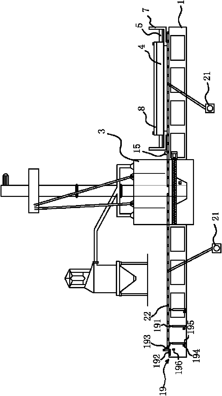
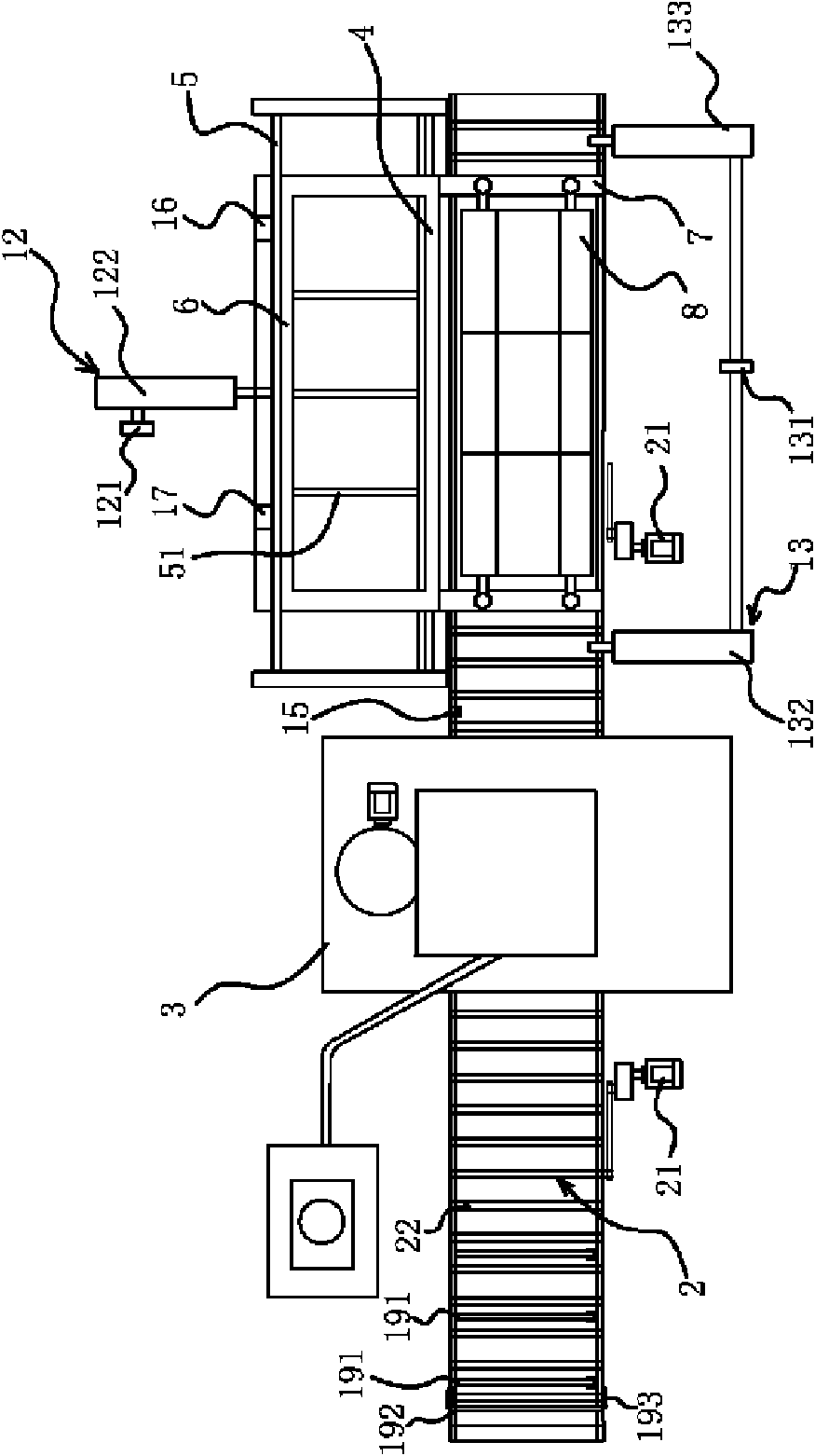
[0033] Such as figure 1 and figure 2 As shown, the steel processing equipment includes a frame 1 , a conveying mechanism 2 installed on the frame 1 capable of conveying steel to be processed, and a processing chamber 3 . The feeding device is arranged at the feeding place of the conveying mechanism 2, and the upper part of the conveying mechanism 2 is provided with a feeding bracket 4, and a flat loading part 5 for placing steel materials to be processed is arranged in the feeding bracket 4, The material carrier 5 can move back and forth along the horizontal direction, and the upper part of the material carrier 5 is provided with a blocking member 6 that blocks the steel to be processed and allows the steel to be processed to drop onto the conveying mechanism 2 .

[0034] The conveying mechanism 2 includes a roller shaft 22 driven by a motor 21 through a chain to rotate, and each roller shaft 22 is horizontally and parallelly arranged on the frame 1, and the roller shaft 22 ...

Embodiment 2

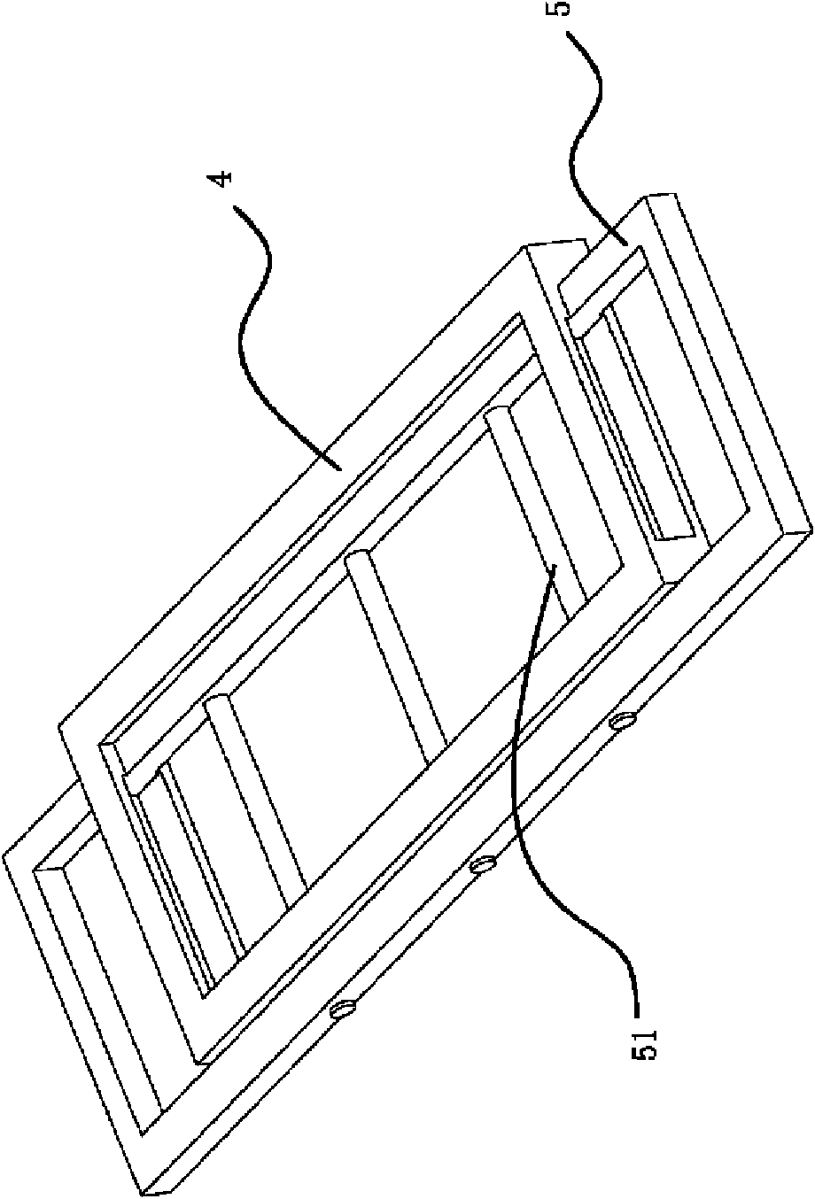
[0045] Such as Figure 5 As shown, the structure and principle of this embodiment are basically the same as that of Embodiment 1. The difference is that the blocking member 6 in this embodiment is fixed above one side of the conveying mechanism 2, and the loading member 5 is located on the other side of the conveying mechanism 2. The top of one side is connected with the power mechanism three 14, and the power mechanism three 14 can push the material carrier 5 to move relative to the feeding bracket 4 and make the steel to be processed fall onto the conveying mechanism 2 under the blocking of the stopper 6. One side of the blocking part 6 is provided with an induction switch three 18 that can contact the side of the loading part 5 when all the steel materials to be processed on the loading part 5 fall, the induction switch three 18 is connected with the power mechanism three 14, and When the material part 5 is in contact with the induction switch, it can generate a control sig...


PUM


Abstract

The invention provides a feeding device in a steel processing device, belonging to the mechanical technical field. The feeding device solves the problems that the existing steel processing device discontinuously loads materials, has low processing efficiency and the like. The feeding device in the steel processing device is characterized in that the steel processing device comprises a frame, a conveying mechanism which is arranged on the frame and can convey steel to be processed, the feeding device is arranged in a feeding part of the conveying mechanism, a feeding bracket is arranged above the conveying mechanism, a platy material carrying part for putting the steel to be processed is arranged in the feeding bracket and moves back and forth along the horizontal direction, and a blockingpart which blocks the steel to be processed and brings down the steel to be processed is arranged above the material carrying part. The feeding device has the advantages of simple and safe operation,high processing efficiency, small occupied area, low manufacture cost and the like.

Description

technical field [0001] The invention belongs to the technical field of machinery and relates to a feeding device, in particular to a feeding device in steel processing equipment. Background technique [0002] The steel to be processed is a variety of pipe-shaped, cylindrical steel-shaped straight steel, which is generally conveyed by the roller shaft set on the frame. The roller shaft is driven by the motor through the chain drive to rotate, and the steel to be processed is conveyed with the rotation of the roller shaft. Enter the processing room for processing. [0003] For example, the Q69 series pass-through (steel structure) shot blasting machine produced by Qingdao Huanghe Machinery Co., Ltd. is a roller table continuous pass-through shot blasting machine, which places a steel pipe or steel bar to be derusted on the roller On the road, the roller table rolls, so that the steel pipe or steel bar enters the blasting chamber for surface treatment. This shot blasting mach...

Claims


Application Information

Patent Timeline
Patent Type & Authority Applications(China)
IPC IPC(8): B23Q7/00
Inventor 刘传玲
Owner 刘传玲
Why Eureka
Try Eureka