Eight-channel DDS signal source board

A signal source, eight-channel technology, applied in the direction of electrical components, transmission systems, etc., can solve the problem of low reference clock

Inactive Publication Date: 2010-03-03
BEIJING INSTITUTE OF TECHNOLOGYGY
View PDF0 Cites 27 Cited by
  • Summary
  • Abstract
  • Description
  • Claims
  • Application Information

AI Technical Summary

Problems solved by technology

[0004] The purpose of the present invention is to overcome the shortcomings of the current multi-channel signal source with few channels and low reference clock, realize the 8-channel DDS signal source board, and solve the phase synchronization problem between multiple channels

Method used


Image

  • Eight-channel DDS signal source board
  • Eight-channel DDS signal source board
  • Eight-channel DDS signal source board

Examples


Embodiment Construction

[0019] Below in conjunction with accompanying drawing and specific embodiment the present invention is described in further detail:

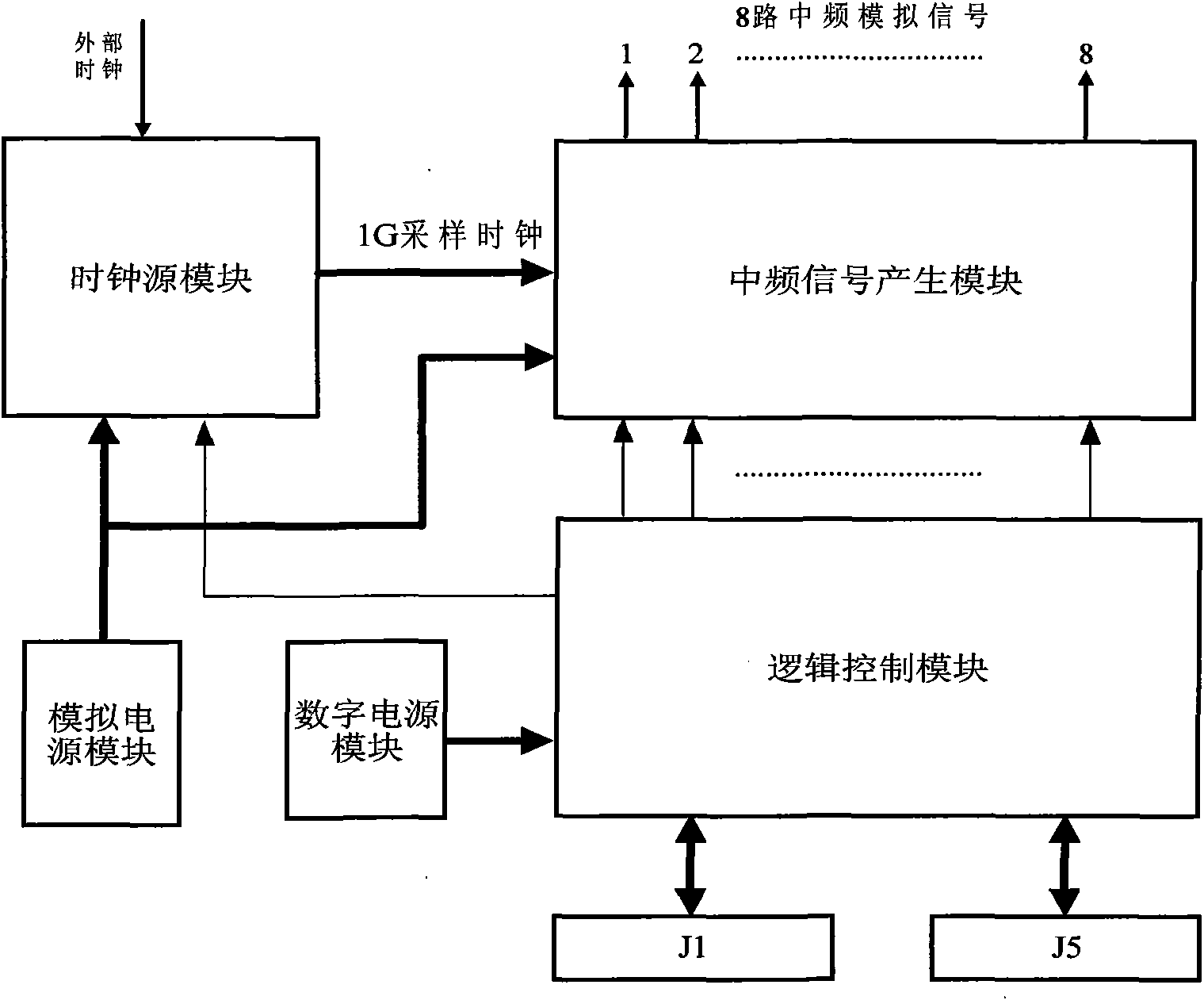
[0020] The block diagram of functional modules of the present invention is shown in figure 1 , including an analog power module, a digital power module, a clock source module, an intermediate frequency signal generation module, and a logic control module.

[0021] Analog power supply module: In consideration of ensuring the quality of the analog signal, the analog power supply uses linear power supply chips, LT1763 and TPS75533 respectively provide voltages of 9V and 3.3V.

[0022] Digital power supply module: The digital power supply includes LT1764EQ-1.8, LT1764EQ-2.5, PTH04000W, providing voltages of 1.8V, 2.5V, and 1.2V.

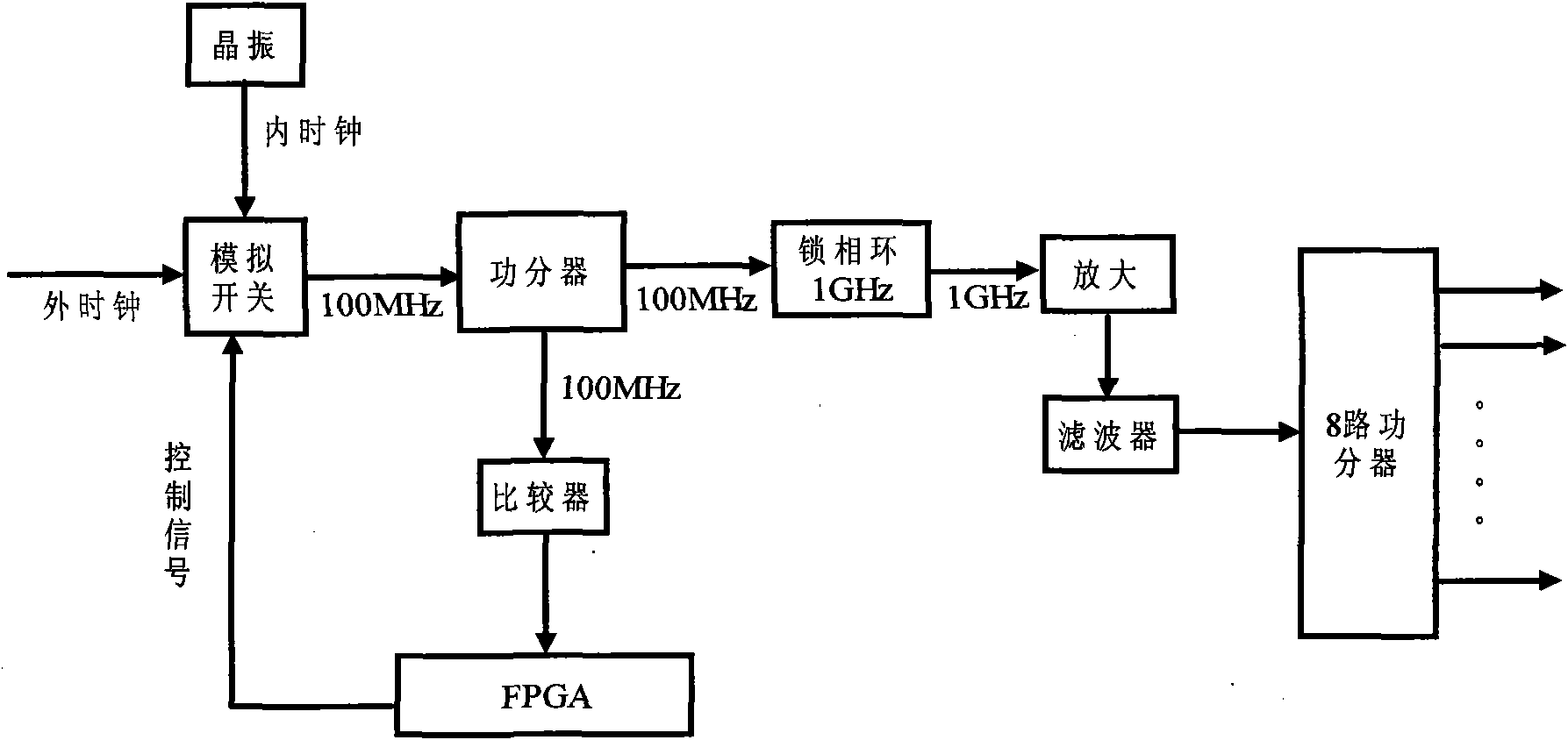
[0023] Clock source module: The structural block diagram of the clock source module is as follows figure 2 Firstly, the 100MHz clock provided inside and outside the board is simultaneously input to the analog switch HSW...


PUM


Abstract

The invention relates to an eight-channel DDS signal source board, belonging to the technical field of digital signal processing. The eight-channel DDS signal source board comprises an analog power supply module, a digital power supply module, a clock source module, an intermediate frequency signal generation module and a logic control module. 0-400 MHz intermediate frequency signals of eight-channel are generated by using a programmable hardware structure and a DDS chip of a 1G reference clock; the eight-channel DDS signal source board is characterized by universality, expandability and capability for being programmed independently for each channel; the software is combined with the hardware to solve the phase synchronization problem among a plurality of channels under condition of usinga high-frequency reference clock; and the signal source board is used for the generation of active phased array radar emitting signals and occasions needing multi-channel and synchronous intermediatefrequency signals.

Description

technical field [0001] The invention relates to a DDS signal source board, which belongs to the technical field of digital signal processing. Background technique [0002] As the required IF signal bandwidth is getting larger and larger, the traditional 100M reference frequency DDS chip has been difficult to meet the requirements. Existing DDS signal source boards usually can only achieve less than 4 channels, and the reference clock of the DDS chip used is relatively low, generally below 500MHz, so the generated signal frequency generally does not exceed 200MHz. "Design of Multi-channel Synchronous DDS Signal Source Based on ISA Bus" in "Application of Electronic Technology" No. 4, 2006 discusses the use of the AD9854 DDS chip of AD Company to realize a signal source with 3 channels and a reference clock of 300MHz; Harbin The 2006 master's degree thesis "Multi-channel phase controllable signal source hardware design" of the University of Technology discussed the use of the...

Claims


Application Information

Patent Timeline
Patent Type & Authority Applications(China)
IPC IPC(8): H04B1/69H04B1/00H04B1/7073
Inventor 李云杰刘浩高梅国张伟
Owner BEIJING INSTITUTE OF TECHNOLOGYGY
Why Eureka
Try Eureka