
Overvoltage online monitoring device based on dual time base sampling technology

A monitoring device and dual time base technology, applied in emergency protection circuit devices, measuring devices, circuit devices, etc. used to limit overcurrent/overvoltage, can solve the problems affecting safety, the sampling rate cannot be flexibly set, and the sampling accuracy is not good. High-level problems, to achieve the effect of improving safety, high measurement accuracy and safety, and improving the ability to resist electromagnetic interference

Active Publication Date: 2010-03-10
SHAANXI ELECTRIC POWER RES INST +2
View PDF1 Cites 16 Cited by
  • Summary
  • Abstract
  • Description
  • Claims
  • Application Information

AI Technical Summary

Problems solved by technology

After searching domestic and foreign patent documents online, the application number is [200510041795.1], and the name is a Chinese invention patent for the online detection method and device of multi-channel transient waveform overvoltage in power system. The device basically consists of a high-voltage divider and a signal conditioning unit , acquisition unit, and industrial computer, which realizes the on-line monitoring of the overvoltage of the power system, but its stability is poor, the anti-interference ability is poor, the accuracy of sampling is not high, the sampling rate cannot be flexibly set, and the measurement circuit is directly electrically connected to the primary equipment. , affecting safety, etc., especially for lightning overvoltage monitoring has certain limitations

Method used


Image

  • Overvoltage online monitoring device based on dual time base sampling technology
  • Overvoltage online monitoring device based on dual time base sampling technology
  • Overvoltage online monitoring device based on dual time base sampling technology

Examples


Embodiment Construction

[0023] The structural principle and working principle of the present invention will be further described in detail below in conjunction with the accompanying drawings.

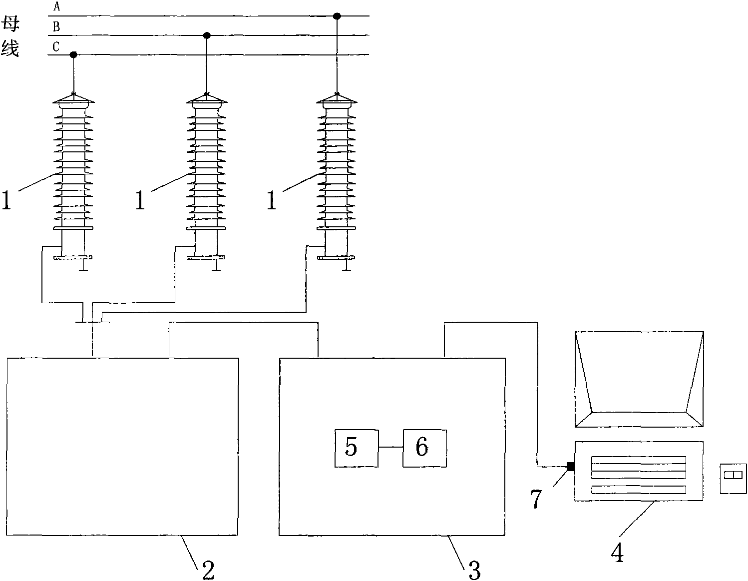
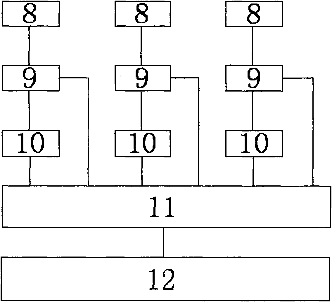
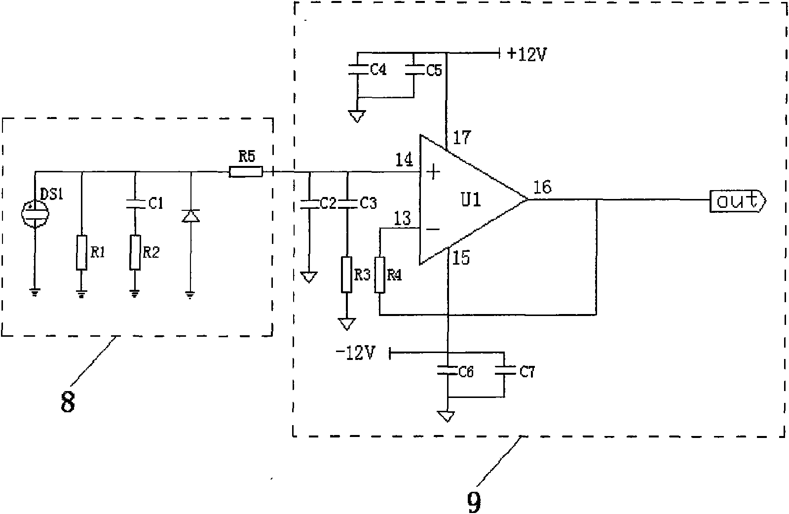
[0024] refer to figure 1 , an overvoltage monitoring device based on dual time base sampling technology, comprising a resistance-capacitance high-voltage sensor 1, the signal output terminal of the resistance-capacitance high-voltage sensor 1 is connected to the double protection circuit input terminal of the signal conditioning unit 2 through a double-shielded coaxial cable Connected, the photoelectric isolation output terminal of the signal conditioning unit 2 is connected with the input terminal of the photoelectric isolation module 5 of the signal isolation unit 3, the output terminal of the photoelectric isolation module 5 is connected with the network port 7 of the industrial control computer 4, and the signal isolation unit 3 The output end of the isolated power supply 6 is connected to the power input ...


PUM


Abstract

The invention relates to an overvoltage online monitoring device based on a dual time base sampling technology, which comprises a resistance-capacitance high-voltage sensor. The signal output end of the resistance-capacitance high-voltage sensor is connected with the input end of a dual protective circuit of a signal-conditioning unit by a double-shielding layer coaxial cable. The photoelectric isolation output end of the signal-conditioning unit is connected with the input end of a photoelectric isolation module of a signal isolation unit. The output end of the photoelectric isolation module is connected with the Ethernet port of an industrial control computer. The output end of an isolation power supply of the signal isolation unit is connected with the power supply input end of the signal-conditioning unit. The signal-conditioning unit internally adopts dual time base data acquisition module redundancy for the collection of an overvoltage signal waveform to not only suitable for monitoring an overvoltage of a power system, but also suitable for monitoring an external overvoltage of the power system, particularly have predominant effect on the lighting overvoltage and improve the accuracy and the stability of overvoltage online monitoring.

Description

technical field [0001] The invention belongs to an on-line overvoltage monitoring device of a power system, in particular to an on-line overvoltage monitoring device based on dual time base sampling technology. Background technique [0002] With the continuous development of power economy and the continuous improvement of users' requirements for power quality, the requirements for power system reliability are getting higher and higher. The reliability of the power system first depends on the reliability of the operation of electrical equipment. However, a large part of the damage accidents of electrical equipment are caused by insulation faults. Among them, the overvoltage of the power grid has a great impact on the insulation of power equipment, which is likely to cause damage to the insulation of power operating equipment, thereby causing power accidents and seriously affecting the power system. safe operation. [0003] Overvoltage is an abnormal voltage exceeding the wo...

Claims


Application Information

Patent Timeline
IPC IPC(8): G01R19/165G01R31/28H02H9/04
Inventor 蒲路马航向杜秦生李修路郑小川梁红军王长安
Owner SHAANXI ELECTRIC POWER RES INST
Learn More