
Method for detecting distortion degree of inrush current of transformer

A detection method and technology of distortion degree, applied in the direction of rate of change measurement, instrument, measurement electricity, etc., can solve the problems of inability to judge the excitation current normally, prone to misoperation or delayed action, unsatisfactory effect, etc., and achieve improvement. The effect of low long-term correct action rate and high judgment accuracy

Inactive Publication Date: 2012-05-30
南京南电继保自动化有限公司
View PDF5 Cites 0 Cited by
  • Summary
  • Abstract
  • Description
  • Claims
  • Application Information

AI Technical Summary

Problems solved by technology

The waveform is symmetrical, that is, the braking method of even-order harmonic braking is unsatisfactory in the case of symmetrical inrush current
In addition, when the transformer is over-excited, its excitation current waveform is symmetrical, and at this time it is impossible to judge the excitation current normally.
[0004] In short, the current methods only reflect the distortion of the inrush current from a certain aspect of the degree of current distortion, and do not fully reflect the distortion of the inrush current. They inevitably have limitations of one kind or another, and the redundancy of the differential protection braking criterion Relatively low margin, prone to malfunction or delayed action

Method used


Image

  • Method for detecting distortion degree of inrush current of transformer
  • Method for detecting distortion degree of inrush current of transformer
  • Method for detecting distortion degree of inrush current of transformer

Examples


Embodiment Construction

[0014] Embodiments of the present invention will be specifically described below.

[0015] Using a high-performance microprocessor, the sampling value of the real-time current of each side and each phase is obtained through analog-to-digital conversion. When the phase current mutation is greater than 0.5Icd, or when the differential current is greater than 0.8Icd, it is judged that the transformer is abnormal.

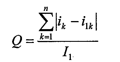
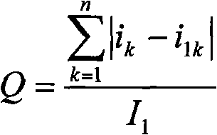
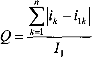
[0016] Utilize the method of the present invention to carry out detection judgment, ask for distortion degree Q,

[0017] Q = Σ k = 1 n | i k - i 1 k | I 1

[0018] I...


PUM


Abstract

The invention provides a method for detecting distortion degree of inrush current of a transformer, which adopts abundant high order harmonic resulting in inrush current distortion in inrush current to comprehensively reflect the distortion degree of the inrush current so as to judge whether fault current or magnetizing inrush current leads the current of the transformer to be abnormal according to the distortion degree. Therefore, the distortion degree Q is defined and the calculation method of Q is declared as follows: filtering out direct current components by a difference algorithm; and filtering out fundamental components by a cosine filter. When the judgment result is the fault current, the numerical values of a front sequence and a rear sequence of the cosine filtering are basically consistent, so the Q value is small; when the judgment result is the magnetizing inrush current, the numerical values of the front sequence and the rear sequence of the cosine filtering have big discrepancy, so the Q value is big. The fault current and the magnetizing inrush current can be strictly distinguished by selecting a valve value properly. The method has higher redundancy on the criterion and can use braking with a logic product door, therefore, differential protection can not act in a delaying manner when being dropped into a transformer in fault. The invention has the advantage ofimproving the condition of low long-term correct action rate of the differential protection of the transformer.

Description

technical field [0001] The invention belongs to the field of relay protection of power systems, is suitable for differential protection of transformers, is used for distinguishing transformer fault currents and excitation inrush currents, and is a distortion detection method for transformer inrush currents. Background technique [0002] Because the guide wire is relatively short, the differential protection is more suitable as the main protection of the transformer, and has good performance. However, when the transformer is air-dropped and closed, an exciting inrush current will be generated, and this exciting inrush current is a differential current, which will cause the differential protection to malfunction. Therefore, measures must be taken to prevent the maloperation of differential protection caused by the excitation inrush current when the transformer is switched on without load. The methods that have been adopted at present include: detecting the content of the seco...

Claims


Application Information

Patent Timeline
Patent Type & Authority Patents(China)
IPC IPC(8): H02H7/04G01R19/12G01R31/00
Inventor 仇资常旭东
Owner 南京南电继保自动化有限公司
Learn More