A fault location method suitable for three-terminal t-connected transmission lines

A technology of transmission line and distance measurement method, which is applied in the direction of fault location, information technology support system, etc., and can solve problems such as inability to locate faults

Active Publication Date: 2011-12-14
NANJING GUODIAN NANZI POWER GRID AUTOMATION CO LTD
View PDF0 Cites 1 Cited by
  • Summary
  • Abstract
  • Description
  • Claims
  • Application Information

AI Technical Summary

Problems solved by technology

[0004] The above-mentioned various fault location methods are all distance measurement calculations when the three-terminal transmission lines are in normal operation. Case
As for the fault location switching scheme before and after the conversion of this operation mode, most of them have not been proposed, and in the two-terminal operation mode and the three-terminal operation mode when one branch is in the hot standby state, the branch on the switch side should be disconnected. When a line fault occurs, none of the existing methods can perform correct fault location

Method used


Image

  • A fault location method suitable for three-terminal t-connected transmission lines
  • A fault location method suitable for three-terminal t-connected transmission lines
  • A fault location method suitable for three-terminal t-connected transmission lines

Examples


Embodiment Construction

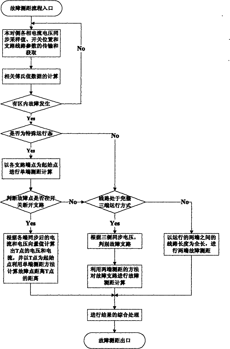
[0047] The present invention can be implemented by a microcomputer protection device capable of three-terminal synchronous sampling. The specific implementation is as follows:

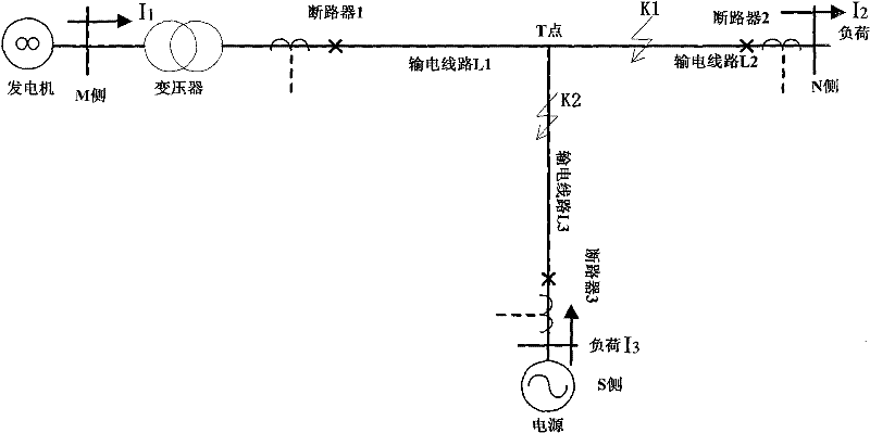
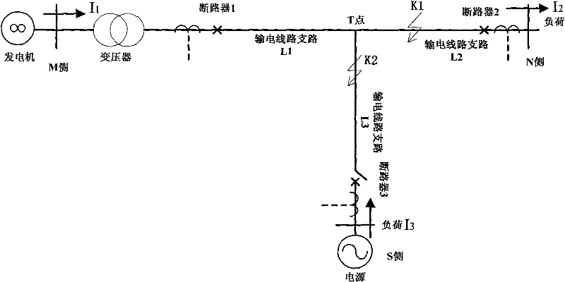
[0048] 1. In the operation of the three-terminal T-connection transmission line of the power system, the phase current and phase voltage of the current and other sides of the three-terminal transmission line are synchronously sampled at a predetermined constant and the same sampling rate (such as figure 1 or figure 2 In the M side, N side and S side), the sampling value of the phase current and phase voltage of the opposite side is transmitted to the local side, and the position of the opposite side switch, the status of the opposite side differential pressure plate and the status of the opposite side differential pressure plate can be judged for the line operation mode. The status of the pressure plate is transmitted to this side when running in the mode.

[0049] 2. Use the full-cycle Fourier algorithm t...


PUM


Abstract

The invention discloses a fault localization method suitable for a three-terminal T connection electric transmission line, comprising the following steps: firstly, judging the running state of the three-terminal electric transmission line: if the line is in a three-terminal running mode, firstly identifying a fault branch line, and calculating the fault distance according to the electric quantityof both ends of a T connection point and the endpoint of the fault branch line; if the line is in a two-terminal running mode or one side branch line is in a three-terminal running mode in a hot standby state, firstly determining if a fault point is at a switch cut-off branch line or not, if so, adopting a single-terminal localization method to calculate the distance from the T connection point tothe fault point, thereby obtaining the fault distance from the endpoint of the branch line to the fault point; but if the fault point is not at the switch cut-off branch line, respectively carrying out fault localization calculation under the two-terminal running mode or the three-terminal running mode. The invention provides a fault localization method before / after converting the running mode ofthe three-terminal electric transmission line and a fault localization method when the line is in the two-terminal running mode or one side branch line is in the three-terminal running mode under thehot standby condition.

Description

Technical field [0001] The invention belongs to the technical field of power system automation, and relates to a fault location method suitable for three-terminal T-connection transmission lines. Background technique [0002] In the high-voltage power grid, with the development of the power system, the increase of load density and the difficulty of land acquisition for new substations, high-voltage and heavy-load three-terminal T-connection transmission lines often appear. In order to speed up the removal of line faults and reduce the economic losses caused by power outages, high-precision fault location technology is required. However, due to the structural particularity of the three-terminal transmission system, it is impossible to determine the location of the fault point on the three-terminal system with the single-terminal electrical fault location method. Although the algorithm of the two-terminal system is relatively mature, it is difficult to The algorithm of the two-ter...

Claims


Application Information

Patent Timeline
Patent Type & Authority Patents(China)
IPC IPC(8): G01R31/08
CPCY04S10/522Y04S10/52
Inventor 张勇刚薛明军朱建红姚亮兰金波
Owner NANJING GUODIAN NANZI POWER GRID AUTOMATION CO LTD
Why Eureka
Try Eureka