Compensation method of pixel data, time sequence controller and liquid crystal display (LCD)

A technology of pixel data and compensation method, applied in static indicators, instruments, etc., can solve the problems of brightness difference of light source, block effect at the boundary of backlight area, etc., and achieve the effect of smooth image

Inactive Publication Date: 2010-03-10
AU OPTRONICS CORP
View PDF0 Cites 32 Cited by
  • Summary
  • Abstract
  • Description
  • Claims
  • Application Information

AI Technical Summary

Problems solved by technology

[0003] However, since the pixel data of the pixels in each pixel area will only be compensated according to the brightness of the light source provided by the corresponding backlight area (that is, a single backlight area), the image finally presented by the liquid crystal display is likely to be different due to The difference in the brightness of the light source provided by each backlight area causes block effect at the boundary of each backlight area

Method used


Image

  • Compensation method of pixel data, time sequence controller and liquid crystal display (LCD)
  • Compensation method of pixel data, time sequence controller and liquid crystal display (LCD)
  • Compensation method of pixel data, time sequence controller and liquid crystal display (LCD)

Examples


Embodiment Construction

[0036] Reference will now be made in detail to embodiments of the invention, examples of which are illustrated in the accompanying drawings. In addition, wherever possible, elements / members / symbols with the same reference numerals are used in the drawings and the embodiments to represent the same or similar parts.

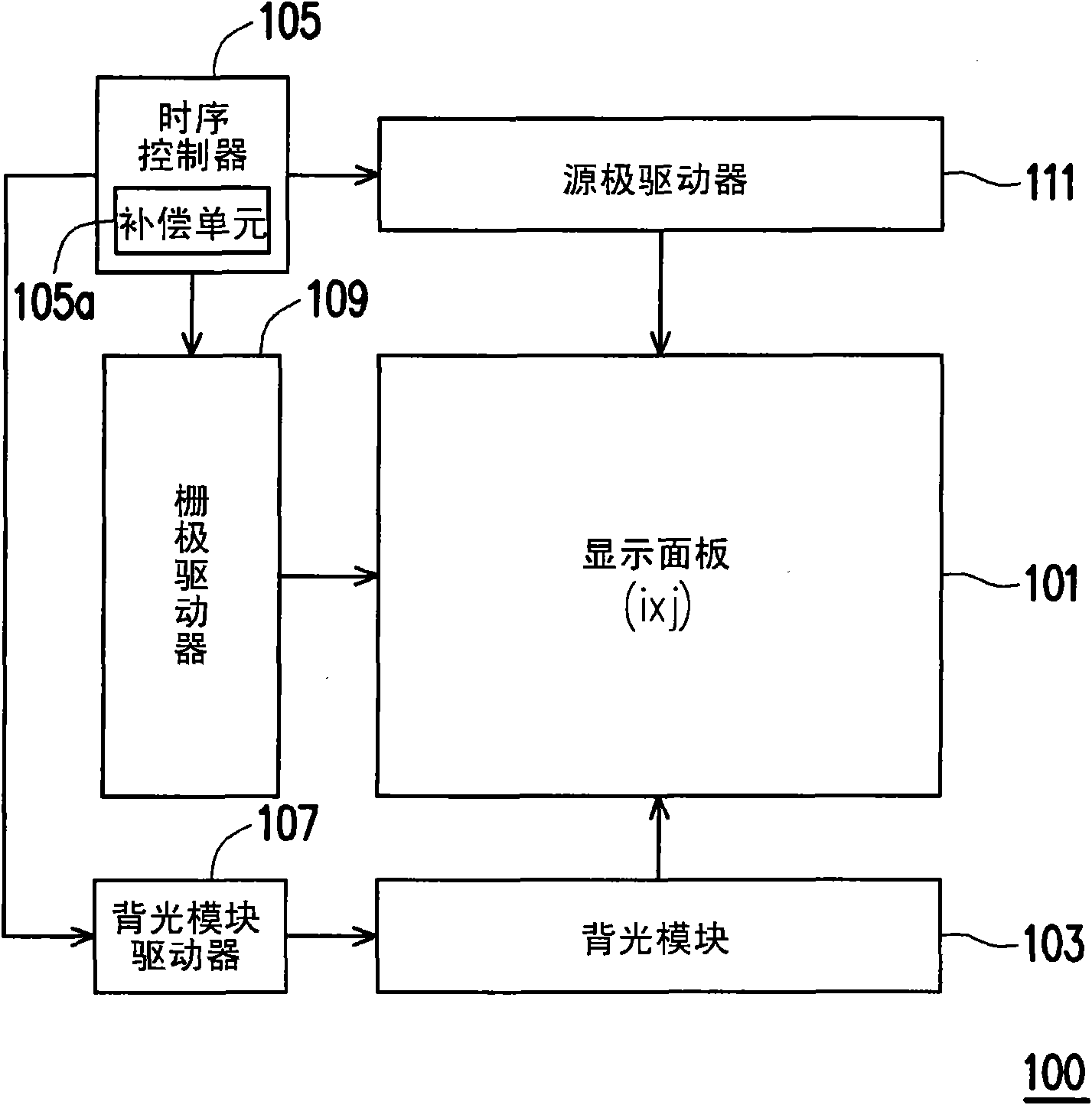
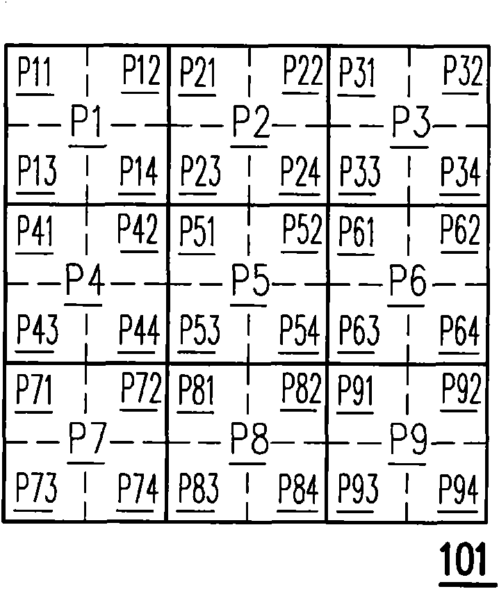
[0037] figure 1 A system block diagram of a liquid crystal display 100 according to an embodiment of the present invention is shown. Please refer to figure 1 The liquid crystal display 100 includes a display panel 101 , a backlight module 103 , a timing controller 105 , a backlight module driver 107 , a gate driver 109 , and a source driver 111 . Wherein, the display panel 101 has a plurality of pixels arranged in a matrix, figure 1 It is represented by i×j.

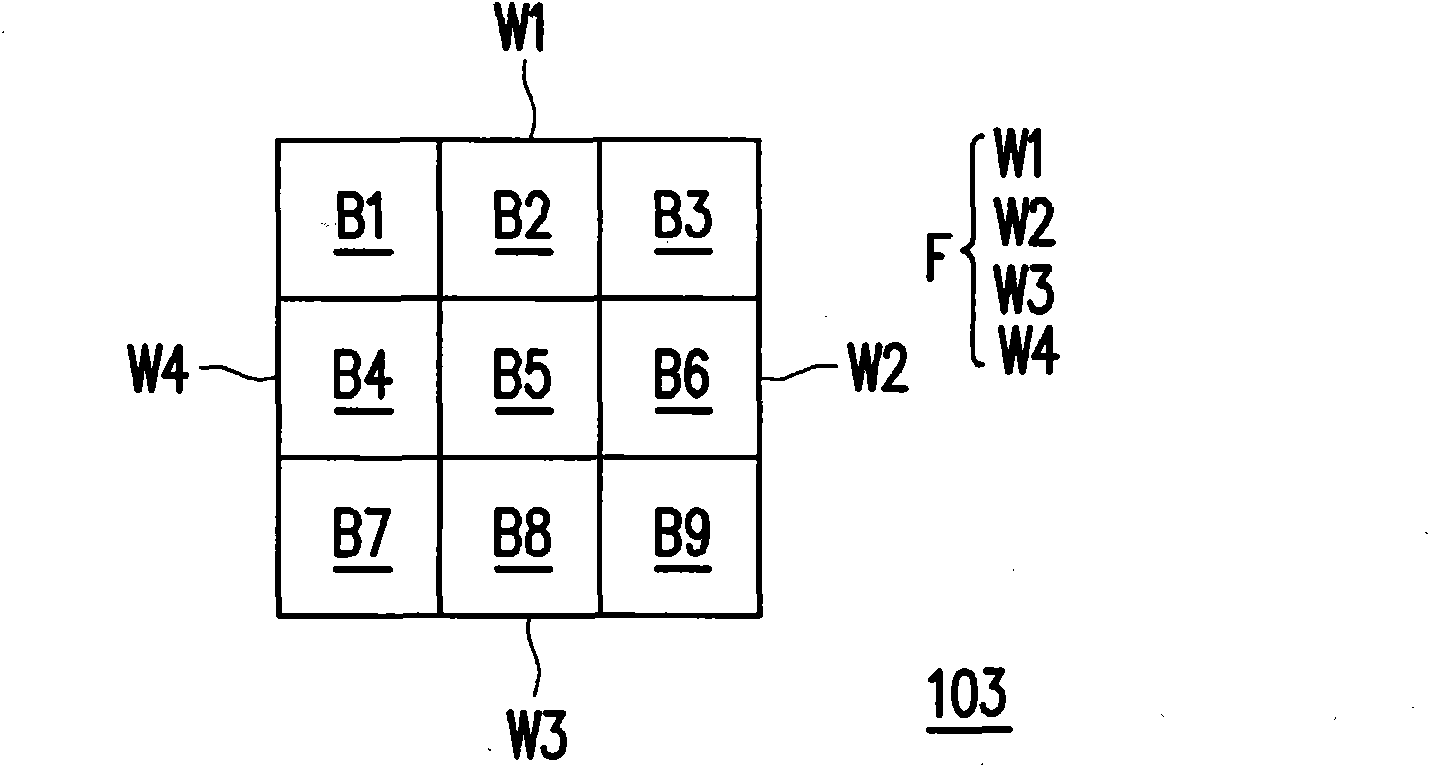
[0038] The backlight module 103 (for example, LED backlight module) has a plurality of backlight regions for providing the backlight required by the display panel 101 . To be more clear, figure 2 Shown...


PUM


Abstract

The invention relates to a compensation method of pixel data, a time sequence controller and a liquid crystal display (LCD). The compensation method comprises: according to the positions of a plurality of backlight areas in a backlight module, determining a first compensation coefficient of each backlight area; according to the way of mutual influence between the position of each pixel in a display panel corresponding to the backlight areas and the backlight areas, determining at least one first compensation coefficient corresponding to each pixel; according to the at least one first compensation coefficient corresponding to each pixel, executing calculation and obtaining a second compensation coefficient of each pixel; and according to the second compensation coefficient of each pixel, respectively compensating the pixel data of each pixel. The image shown by the invention can avoid block artifact effect at the boundary dividing lines of the backlight areas caused by the difference inthe brightness of light sources provided by the backlight areas, thus ensuring the finally shown image to be comparatively smooth.

Description

technical field [0001] The invention relates to a plane display technology, and in particular to a compensation method and a timing controller for applying high dynamic range display technology to pixel data of a liquid crystal display. Background technique [0002] Generally speaking, in order to apply high dynamic range (high dynamic range, HDR) display technology to liquid crystal display (liquid crystal display, LCD), usually the backlight module (backlight module) will be divided into a plurality of backlight areas (that is, M*N zone backlight structure) for local dimming. Once the brightness of the light source provided by each backlight area is determined, the pixel data of the pixels in the pixel area corresponding to each backlight area will be compensated accordingly, so that the combination of the two can display a target image. [0003] However, since the pixel data of the pixels in each pixel area will only be compensated according to the brightness of the ligh...

Claims


Application Information

Patent Timeline
Patent Type & Authority Applications(China)
IPC IPC(8): G09G3/20G09G3/36
Inventor 许浩中简民峰叶斯哲
Owner AU OPTRONICS CORP
Why Eureka
Try Eureka