Brightness regulating circuit

A kind of brightness adjustment and circuit technology, applied in the direction of electric lamp circuit layout, electric light source, lighting device, etc., can solve the problems of poor visual experience, inconsistent brightness of light-emitting diodes, etc., and achieve the effect of brightness balance

Inactive Publication Date: 2010-03-10
KUNDA COMP TECHKUSN
View PDF3 Cites 3 Cited by
  • Summary
  • Abstract
  • Description
  • Claims
  • Application Information

AI Technical Summary

Problems solved by technology

Inconsistent brightness of LEDs will bring bad visual experience to users

Method used


Image

  • Brightness regulating circuit

Examples


Embodiment Construction

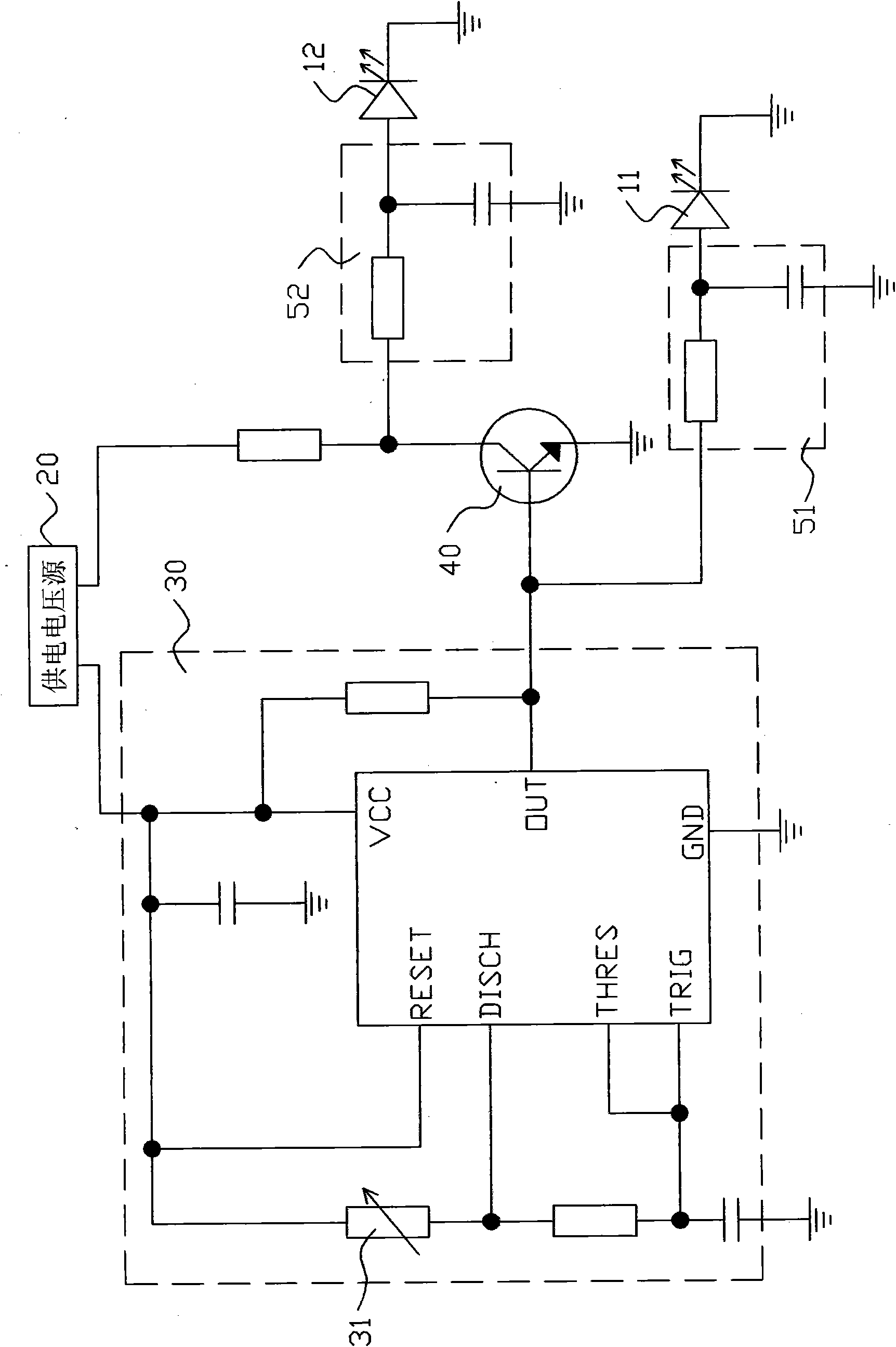
[0008] Please refer to figure 1 As shown, the brightness adjustment circuit of the present invention is used to synchronously adjust the brightness of the first light-emitting element 11 (which may be a light-emitting diode) and the second light-emitting element 12 (which may be a light-emitting diode), and the brightness adjustment circuit includes a power supply voltage source 20, The power supply voltage source 20 is used to provide a power supply voltage; and the power supply voltage source 20 is connected to a pulse wave generator 30, and the pulse wave generator 30 is used to output alternately changing modulation waves, and the modulation waves include peaks and trough, and the pulse generator 30 is provided with a variable resistor 31 (can be a sliding rheostat), by changing the size of the variable resistor 31 to adjust the width of the peak, and the size of the variable resistor 31 is proportional to the width of the wave peak change in the same direction; the pulse ...


PUM


Abstract

The invention provides a brightness regulating circuit, which is used for synchronously regulating the brightness of a first light-emitting component and a second light-emitting component, and comprises a power supply voltage source connected with a pulse generator, wherein the pulse generator is used for outputting a modulation wave which comprises a wave crest and a wave trough; a variable resistor is arranged in the pulse generator, and the size of the variable resistor changes in the same direction of the width of wave crest; the pulse generator is connected with a base electrode of a triode; a collector electrode of the triode is connected with the power supply voltage source; an emitter of the triode is grounded; the collector electrode of the triode acquires an out-phasing modulation wave; the pulse generator is also connected with one end of a first integral circuit, while the other end of the first integral circuit is connected with an anode of the first light-emitting component; and the collector electrode of the triode is connected with one end of a second integral circuit, while the other end of the second integral circuit is connected with an anode of the second light-emitting component. Through the regulation of the variable resistor, the brightness of different light-emitting components can reach balance.

Description

【Technical field】 [0001] The invention relates to a brightness adjustment circuit, in particular to a brightness adjustment circuit which can balance the brightness of different light-emitting elements. 【Background technique】 [0002] Light-emitting diodes are usually used as indicator lights of electronic devices, and users can judge the working status of the electronic devices by observing whether the indicator lights are on or not. The brightness of the light-emitting diode is related to the magnitude of the current flowing through it. When the current flowing through is larger, the brightness of the light-emitting diode is brighter, and when the current flowing through it is smaller, the brightness of the light-emitting diode is darker. [0003] There are often inconsistencies in brightness between different LEDs on the same electronic device. For example, a mobile phone has two LEDs side by side. Under normal working conditions, one of the LEDs is very bright, while the...

Claims


Application Information

Patent Timeline
Patent Type & Authority Applications(China)
IPC IPC(8): H05B37/02
Inventor 许世法
Owner KUNDA COMP TECHKUSN
Why Eureka
Try Eureka