Microfluid conveying and atomizing device

An atomization device and microfluidic technology, applied in the direction of electric solid devices, semiconductor devices, semiconductor/solid device components, etc., can solve problems such as inability to meet thin requirements, complex structure, and large volume of suction pumps

Active Publication Date: 2010-03-10
MICROJET TECH
View PDF0 Cites 17 Cited by
  • Summary
  • Abstract
  • Description
  • Claims
  • Application Information

AI Technical Summary

Problems solved by technology

[0006] The main purpose of the present invention is to provide a microfluid transport and atomization device to solve the known method of cooling heating elements through pumps and heat exchangers. In addition to the limited he

Method used


Image

  • Microfluid conveying and atomizing device
  • Microfluid conveying and atomizing device
  • Microfluid conveying and atomizing device

Examples


Embodiment Construction

[0019] Some typical embodiments embodying the features and advantages of the present invention will be described in detail in the following description. It should be understood that the present invention can have various changes in different aspects, which do not depart from the scope of the present invention, and the descriptions and icons therein are essentially for illustrative purposes, rather than limiting the present invention. invention.

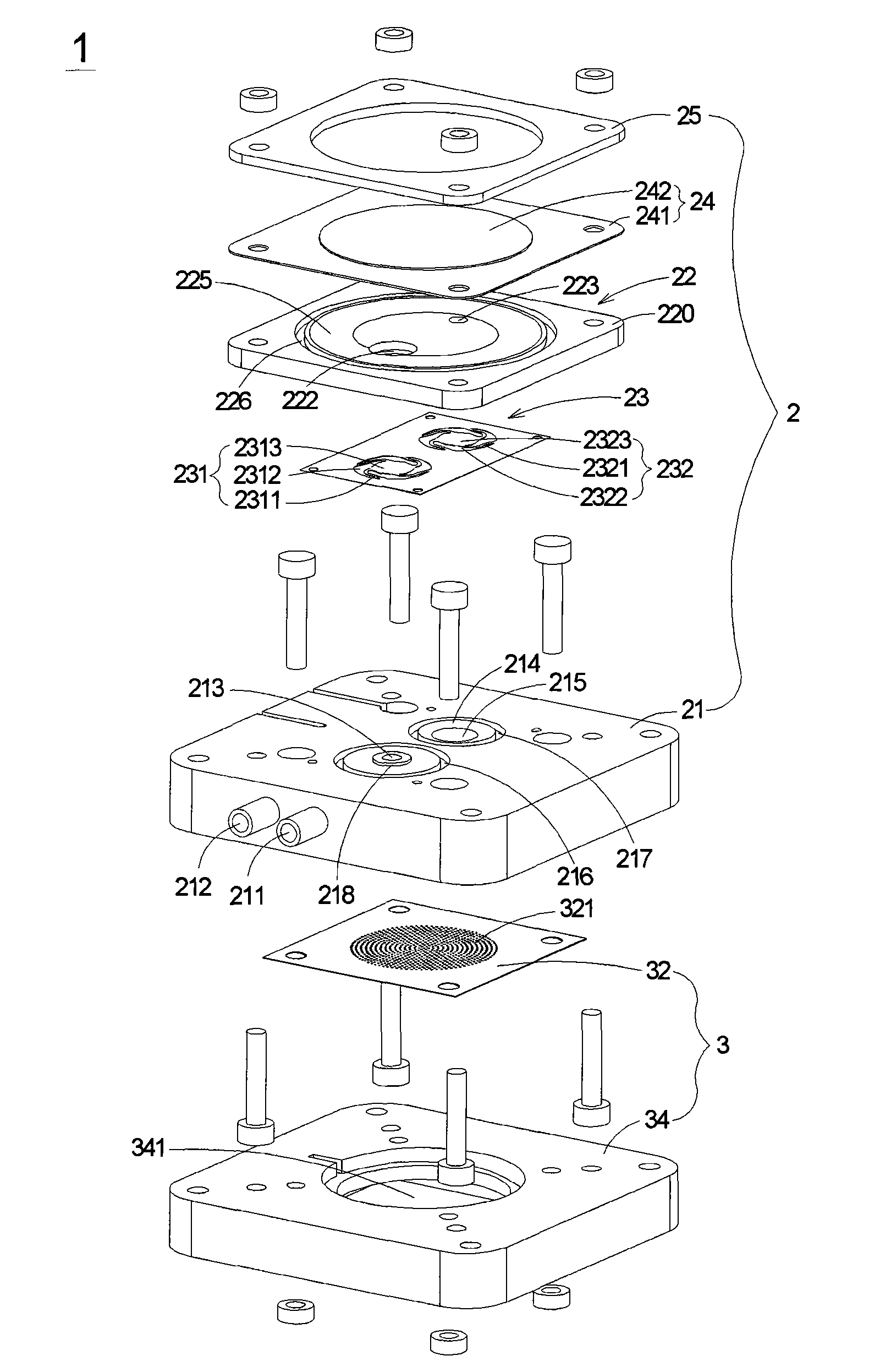
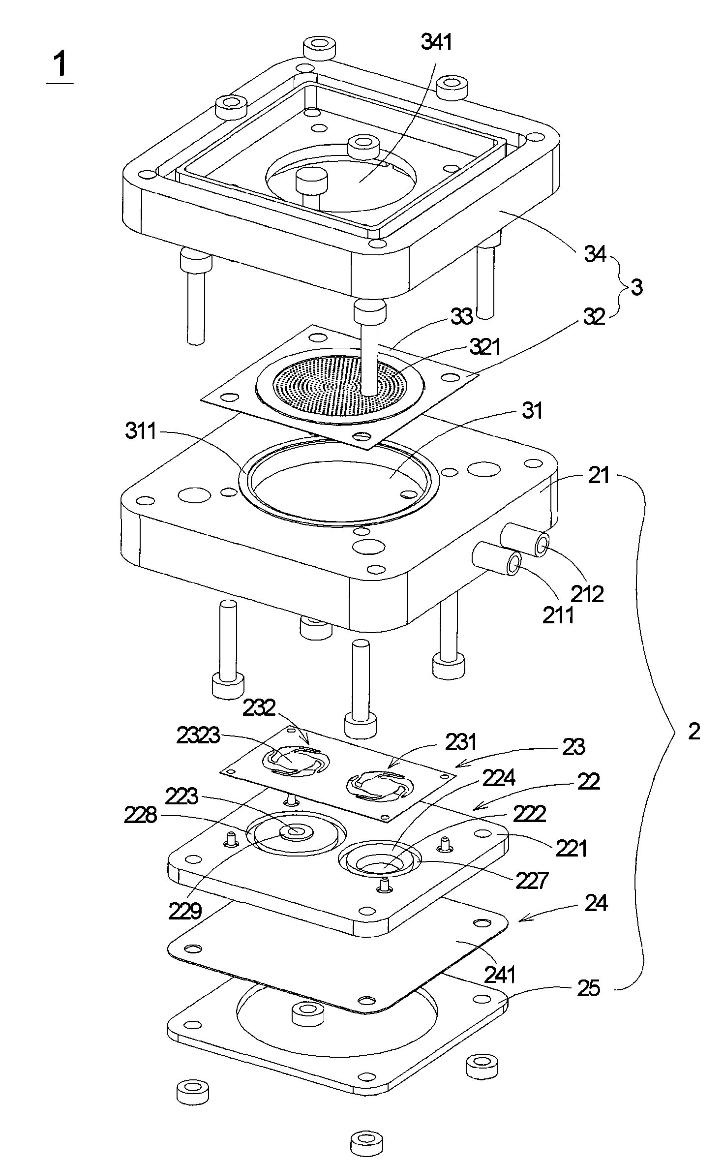
[0020] See Figure 1A and Figure 1B ,among them Figure 1A It is a schematic diagram of the front exploded structure of the microfluid delivery and atomization device of a preferred embodiment of the present invention, Figure 1B Then Figure 1A As shown in the figure, the microfluidic transport and atomization device 1 of the present invention is mainly composed of a microfluidic transporter 2 combined with an atomizer 3, wherein the microfluidic transporter 2 is mainly composed of The valve body seat 21, the valve body cover 22, the valv...


PUM


Abstract

The invention relates to a microfluid conveying and atomizing device used for conveying fluid, atomizing the fluid into a plurality of liquid drops and jetting the liquid drops. The device comprises amicrofluid conveyor and an atomizer, wherein the microfluid conveyor is provided with an entryway; the atomizer is provided with a nozzle piece, a storage groove and an actuating element, and the nozzle piece is arranged corresponding to the storage groove and is connected with the actuating element; and the microfluid conveyor is achieved as follows: fluid is conveyed the storage groove of the atomizer through the entryway to enable the nozzle piece to atomize the fluid into a plurality of the liquid drops to be jetted corresponding to the drive of the actuating element .

Description

Technical field [0001] The invention relates to a microfluid delivery and atomization device, especially a microfluid delivery and atomization device suitable for heat dissipation of electronic components. Background technique [0002] In recent years, computer systems have gradually become an indispensable device in people’s daily lives. There is a motherboard inside to maintain the operation of the entire computer system. However, the heating elements on the motherboard, such as the CPU, will generate A large amount of heat. If the heat cannot be transferred to the outside and accumulated in the housing, it will not only reduce the life of the heating element or even damage it, but also reduce the operating performance of the entire computer system. Therefore, in order to maintain the life of the computer system and For efficiency, an appropriate heat dissipation mechanism is usually adopted on the motherboard to transfer heat to the outside world. [0003] The current heat diss...

Claims


Application Information

Patent Timeline
IPC IPC(8): H05K7/20G06F1/20H01L23/473
Inventor 陈世昌张英伦余荣侯邱士哲周宗柏
Owner MICROJET TECH
Why Eureka
Try Eureka