

Occipital screw rod connector
A connector and occipital technology, applied in the field of medical devices, can solve the problems of inconvenient installation and operation, inconvenient operation, different sizes, etc., and achieve the effect of convenient and smooth use and convenient operation
Inactive Publication Date: 2010-03-17
郭谦
View PDF1 Cites 7 Cited by
- Summary
- Abstract
- Description
- Claims
- Application Information
AI Technical Summary
Problems solved by technology
The insertion method is inconvenient to install and operate. Once the connecting elements 22 and 24 need to be taken out, the position of the plate 42 may be misplaced, which is not only inconvenient to operate, but may also cause certain injuries to the patient.
2. The distance between the combination elements 46 and 48 is fixed and cannot be adjusted during the operation, so it cannot be applied to different groups of people
3. The direction of the channels of the connecting elements 46 and 48 is not adjustable during the operation, and the curved connecting elements 22 and 24 are not easy to insert into the above channels, which will cause difficulties for the doctor during the operation
4. Human occipital bones are different in size, and the size of the plate 42 cannot be changed during the operation, which brings trouble to the surgeon
Method used
View moreImage
Smart ImageViewing Examples

Examples
Embodiment Construction
Login to View More PUM
 Abstract
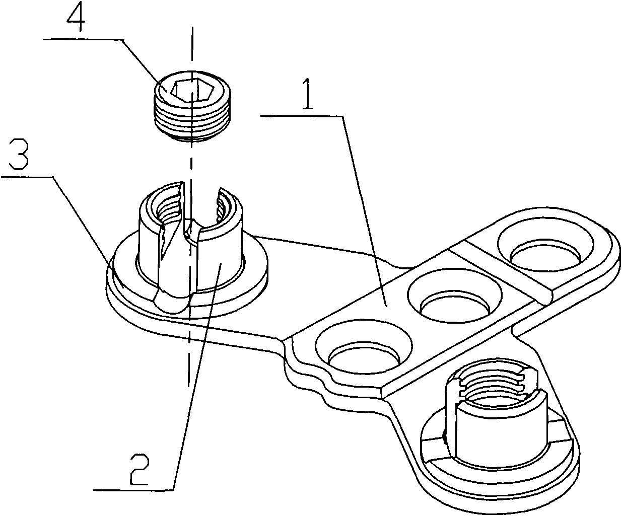
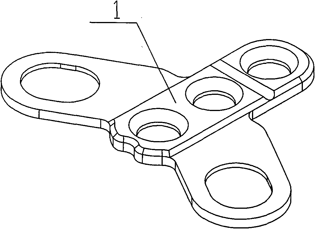
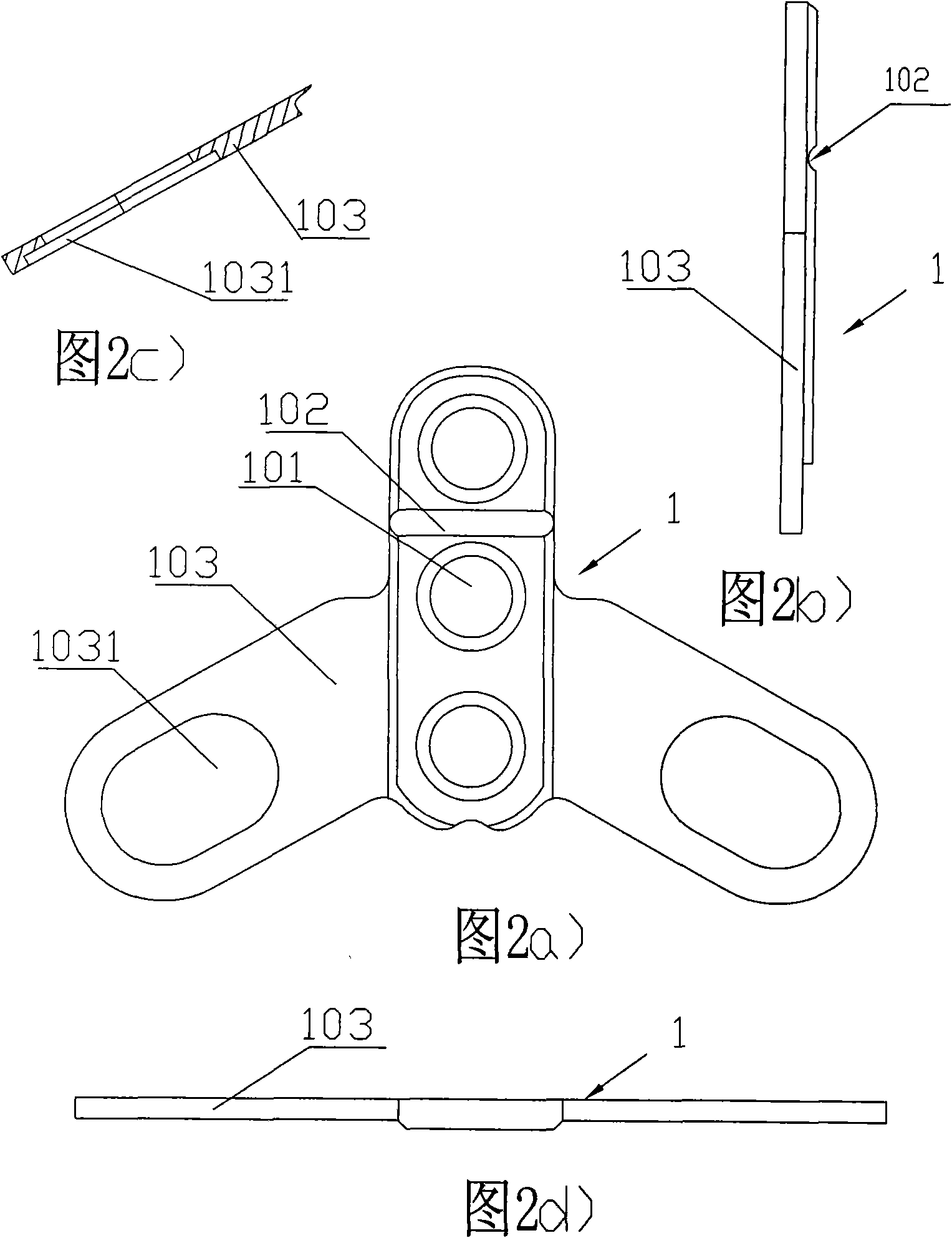
The invention discloses an occipital screw rod connector which consists of an occipital plate, a U-shaped connecting base, a screw plug and a retainer ring, wherein the occipital plate is a swallow-shaped triplex plate with a straight plate in the middle and oblique arm plates at two lower sides, the straight plate is provided with a group of screw holes in which occipital screws are screwed, theoblique arm plate is provided with an elongated slot for adjustment; the U-shaped connecting base is provided with a U-shaped opening groove for receiving a connecting rod in need of connection, a U-shaped opening inner hole of the U-shaped connecting base is provided with the screw plug, and the bottom part of the U-shaped connecting base is provided with an outer edge platform; and the retainerring is an opening-type gasket. The occipital plate and the U-shaped connecting base can be connected into one body with the retainer ring, and the U-shaped connecting base can be movable and rotatable along the elongated slot of the oblique arm plate. When the connecting rod in need of connection is placed in the U-shaped groove of the U-shaped connecting base and the screw plug is screwed, the occipital plate, the U-shaped connecting base, the opening-type retainer ring and the connecting rod can be firmly fixed together.
Description
technical field The invention relates to a medical device technology, in particular to an occipital nail-rod connector used in an orthopedic spinal internal fixator system. technical background In orthopedic spinal orthopedic clinical operations, it is sometimes necessary to use a cervical occipital, thoracic, and posterior fixation system to meet the surgical needs when the condition is serious, the operation is complicated, and the operation is difficult. A complete occipitocervical, thoracic, and posterior internal fixation system typically has two options in clinical practice: a "well" shape (see Figure 7) or a rocket-like structure (see Figure 8). Structurally, the posterior internal fixation system of the occipital cervicothoracic spine consists of four parts: the occipital screw plate, the pedicle screw, the longitudinal connecting rod connecting the pedicle screw and the occipital plate, and the transverse connecting rod connecting the longitudinal connecting rod d...
Claims
Login to View More Application Information
Patent Timeline
 IPC IPC(8): A61B17/70
Inventor郭谦
Owner郭谦