Storage container for substrate and substrate conveying device for the storage container

A technology for storing containers and substrates, applied in lighting and heating equipment, conveyor objects, transportation and packaging, etc., can solve the problems of difficult transfer of substrates, complex structure of cover parts, close proximity of container main body, etc., and achieve a simplified structure Effect

Inactive Publication Date: 2010-03-17
DAIFUKU CO LTD
View PDF1 Cites 11 Cited by
  • Summary
  • Abstract
  • Description
  • Claims
  • Application Information

AI Technical Summary

Problems solved by technology

[0006] However, in the above-mentioned conventional substrate storage container, a plurality of plate-shaped swing plates swingable around the horizontal axis are arranged in a plurality of vertical directions on the portion of the cover member that faces the opening. Complicated components
[0007] In addition, when the substrate is transferred by the substrate transfer device, there is a cover member between the container main body and the substrate transfer device, so the container body cannot be very close to the substrate transfer device due to the existence of the cover member, so the container body cannot be very close to the substrate transfer device. The stroke required for the transfer device to transfer the substrate to the storage container is long, so it is difficult to transfer the substrate by the substrate transfer device
In addition, since the substrate is to be transferred to the storage container with the cover member attached, it is necessary to transfer the substrate through the substrate transfer gap formed in the cover member without interfering with the cover member. It is difficult to transfer the substrate of the substrate transfer device

Method used


Image

  • Storage container for substrate and substrate conveying device for the storage container
  • Storage container for substrate and substrate conveying device for the storage container
  • Storage container for substrate and substrate conveying device for the storage container

Examples


no. 1 approach

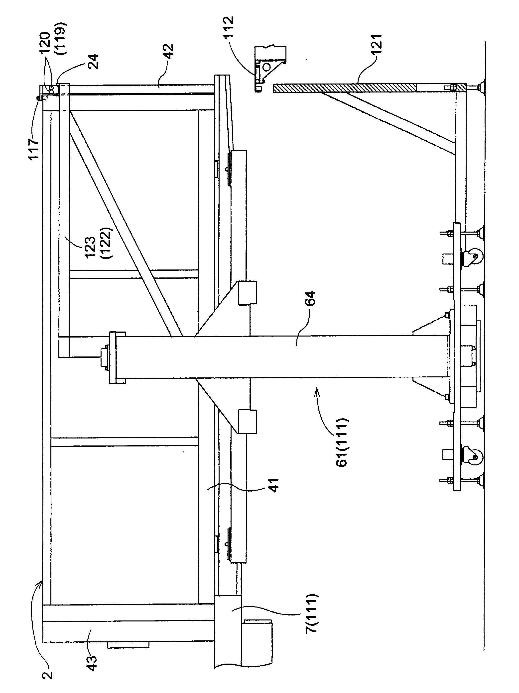
[0134] like figure 1 As shown, the substrate transport equipment is provided with: a container transport mechanism 111 for transporting a storage container 2 as a substrate storage container; a substrate transfer device 112 for transferring a substrate 1 relative to the storage container 2 transported by the container transport mechanism 111 .

[0135] Furthermore, the substrate transfer device 112 is configured to take out the substrate 1 from the storage container 2 conveyed by the container conveyance mechanism 111 and store the substrate 1 in the storage container 2, and is configured to transfer the substrate 1 from the storage container 2. 1 and storage of the substrate 1 in the storage container 2.

[0136] In addition, the substrate of this embodiment is a rectangular substrate used for a glass substrate of a liquid crystal display or a plasma display, or the like.

[0137] [storage container]

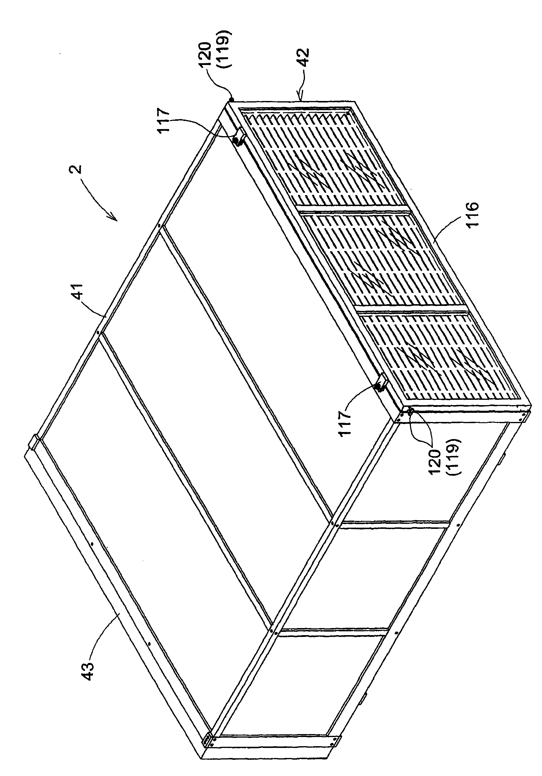
[0138] like figure 1 and figure 2 As shown, the storage container 2 ...

no. 2 approach 》

[0194] "Second embodiment" plate-shaped body support type

[0195] Hereinafter, a second embodiment of a substrate transfer facility to which the substrate storage container of the present invention is applied will be described with reference to the drawings.

[0196] In addition, since the second embodiment has the same configuration as the first embodiment except for the configuration of the supported portion 119, the same reference numerals are attached to the same configurations as those of the first embodiment to omit description, and the main description is different from that of the first embodiment. way of composition.

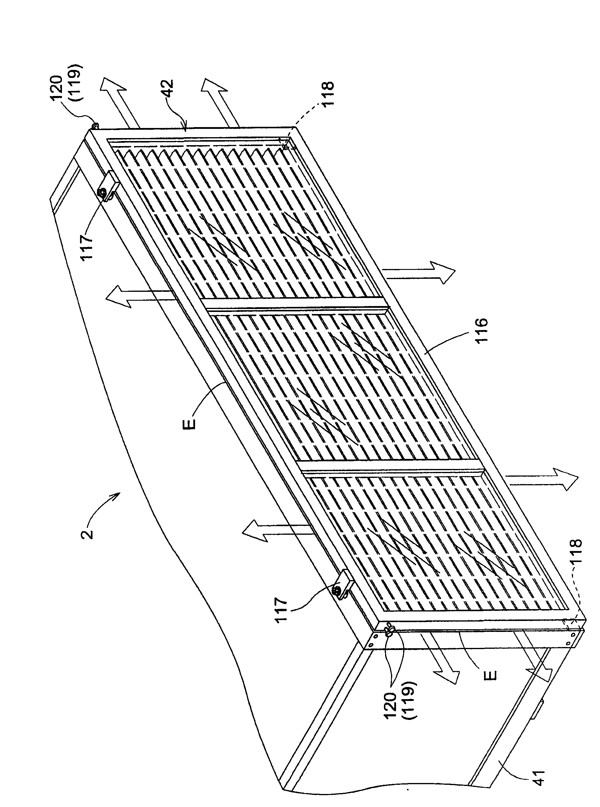
[0197] like Figure 8 As shown, on the lid member 42 , supported portions 119 are provided in a state in which they protrude from the lid body 116 outward in the width direction and the container body side on both sides in the width direction of the upper end portion of the lid body 116 .

[0198] The supported portion 119 is formed of a plate-shaped...

no. 3 approach 》

[0201] "Third Embodiment" frame support type

[0202] Hereinafter, a third embodiment of a substrate transfer facility to which the substrate storage container of the present invention is applied will be described with reference to the drawings.

[0203] In addition, since the third embodiment has the same configuration as the first embodiment except for the configurations of the engaging portion 114, the engaged portion 115, the supported portion 119, and the receiving support body 123, it is the same as the first embodiment. The same reference numerals are attached to the configurations, and the description thereof will be omitted, and the configurations different from the first embodiment will be mainly described.

[0204] like Figure 20 As shown, the engaged portion 115 of the lid member 42 is constituted by an engaged frame 46 provided on the upper end portion of the lid body 116 in a state protruding from the lid member 42 toward the container body side. .

[0205] T...


PUM


Abstract

The present invention provides a storage container for a substrate, which can realize structure simplification of a cover component and facilitates the conveying of substrate. The storage container comprises the following components: a container body (41) which is provided with an opening for storing and taking substrates out at one end and is internally provided with a plurality of substrates; and a cover component (42) which is detachably installed from the upper side relatively to the container body (41) and closes the whole opening at a state of being installed to the container body (41).The cover component (42) is provided with a clamped part (115) which is positioned to a clamping part (114) of the upper part of one end of the container body (41). At the state of being installed tothe container body, the cover component is rotatable around a transverse shaft center along a transverse width direction which intersects the arrangement direction of the container body (41) and the cover component (42), and is installed to the container body (41) at a state that the side of the container body (41) is applied with force.

Description

technical field [0001] The present invention relates to a storage container for a substrate that stores a plurality of substrates in a horizontal posture at intervals in the vertical direction. Background technique [0002] The above-mentioned substrate storage container is a device used when a plurality of substrates are stored in the container main body and the plurality of substrates are collectively transported. [0003] As a conventional example of such a substrate storage container, there is a configuration that has a container body that is formed in a cylindrical shape in a horizontal posture, has an opening for transferring a substrate at one end thereof, and accommodates a plurality of substrates therein. , and a cover member that closes the entire surface of the opening. On the part of the cover member that faces the opening of the container body, a plurality of swing plates that can swing around the horizontal axis are arranged in a row along the vertical directio...

Claims


Application Information

Patent Timeline
Patent Type & Authority Applications(China)
IPC IPC(8): B65D85/48B65D81/00B65G1/04B65G49/06H01L21/673H01L21/677
CPCB65D85/48B65G49/062B65G49/063H01L21/6734H01L21/67379H01L21/67389
Inventor 池畑淑照
Owner DAIFUKU CO LTD
Why Eureka
Try Eureka