
Hydraulic sealing pressure buffer filter

A hydraulic sealing and filter technology, applied in the direction of engine sealing, engine components, mechanical equipment, etc., can solve the problems affecting the quality and clean appearance of the oil cylinder, unable to seal and scrape oil, and not completely solving the sealing ring, etc. Excellent filtering and anti-fouling, excellent sealing performance, not easy to stick to oil and foreign matter

Inactive Publication Date: 2011-04-06
段黎明
View PDF0 Cites 0 Cited by
  • Summary
  • Abstract
  • Description
  • Claims
  • Application Information

AI Technical Summary

Problems solved by technology

[0005] However, the approval of the above-mentioned structure still does not completely solve the sealing ring 9 (Y, U, K and other shapes) under the instantaneous high-pressure impact of starting, can rely on the internal pressure of the oil cylinder to provide enough expansion force for the sealing ring 9, and exert a complete seal. The problem of effect and effect is that the reason is that the Ster seal is installed in the front, and the sealing effect is caused first, so that the sealing ring 9 installed in the back can only rely on its own interference, and only play the role of making up for sealing and scraping oil. Effect, if you encounter the defects of the piston rod 10 (straight corrugation, spiral and local scars, etc.), the compensation effect of the sealing ring will not be obtained, resulting in the oil penetrating from the sealing part of the Ster seal (the inner ring of the Ster seal is relatively small) hard, changes slightly with the shape, and cannot seal the piston rod with convex and concave defects), the sealing ring 9 cannot achieve the effect of sealing and scraping oil without the action of tension, and when the piston rod moves back and forth in a straight line, the piston rod There will be oily phenomenon. In most cases, after working for a long time and repeated back and forth movements, the oil ring at the end of the piston rod will be heavy, and there will be oil dripping for a long time or the surrounding oil will be heavy, which will affect the quality and appearance of the cylinder.

Method used


Image

  • Hydraulic sealing pressure buffer filter
  • Hydraulic sealing pressure buffer filter
  • Hydraulic sealing pressure buffer filter

Examples


Embodiment Construction

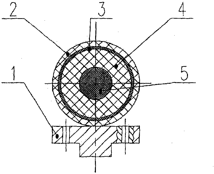
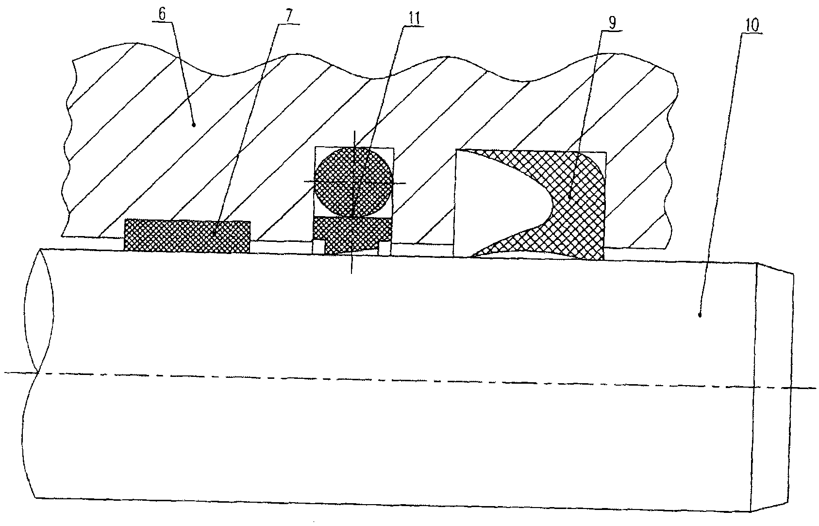
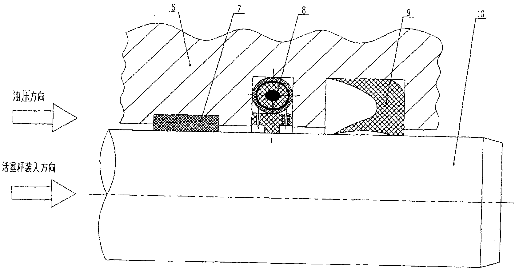
[0031] figure 1 Shown is an embodiment of the hydraulic seal pressure buffer filter of the present invention, which includes a filter body ring and a support body ring 1. The filter body ring is composed of a multi-layer composite mesh ring set outside the matrix, and the matrix is ​​PTFE. Type ring 5, the peripheral multi-layer composite mesh ring is a nylon mesh mesh ring 4 that is set outside the rubber O-ring 5, a metal mesh mesh ring 3 that is set outside the nylon mesh mesh ring 4, and a suit The protective nylon mesh mesh ring 2 outside the metal mesh mesh ring 3; the three mesh rings are all bent into rings by plane mesh, and bonded or welded at the joints. The support body ring 1 is a circular body of composite material, and this embodiment is a polytetrafluoroethylene composite material ring. The filter ring is placed on the support ring 1 . The hydraulic seal pressure buffer filter of the present invention is installed in the groove opened on the guide sleeve 6 ,...


PUM


Abstract

A hydraulic sealing pressure buffer filter belongs to sealing devices of piston rods in engineering hydraulic cylinders. The filter comprises a filter body ring and a support body ring, the filter body ring is formed by sheathing a multi-layer composite mesh ring outside a matrix, the matrix is a rubber O-ring; a nylon wire mesh ring, a metal wire mesh ring and a protective nylon wire mesh ring are sequentially sheathed to form the peripheral multi-layer composite mesh ring. The support body ring is a circular body of a composite material, the filter body ring is circularly arranged on the support body ring; the hydraulic sealing pressure buffer filter is mounted in a groove arranged on a guide sleeve, and the guide sleeve is sheathed outside a piston rod. The filter can meet design requirements of seal rings (of Y shape, U shape, K shape and the like), prolong service life of the seal rings, not be damaged by transient high pressure and foreign materials, cause foreign materials to not remain in the seal rings, improve sealing effect, and effectively relieve transient high pressure.

Description

technical field [0001] The invention relates to a sealing device for a piston rod in an engineering hydraulic oil cylinder, in particular to a hydraulic sealing pressure buffer filter. Background technique [0002] At present, in the engineering hydraulic cylinder industry at home and abroad, in the sealing of the guide sleeve and the piston rod, the typical piston rod sealing structure adopts a front (rear) guide ring, a step seal, a sealing ring (Y, U, K, etc. shape), Structural forms such as dust rings are placed in sequence. In recent years, most of the design manuals of hydraulic cylinders at home and abroad and the actual use and manufacture of each cylinder have this structure. Typical structure such as figure 2 As shown, the step seal 11 , sealing ring 9 and guide ring 7 are sequentially installed on the guide sleeve 6 sleeved on the piston rod body 10 . [0003] In the wide application of this piston rod seal structure, its biggest feature is that Step seal 11 ha...

Claims


Application Information

Patent Timeline
Patent Type & Authority Patents(China)
IPC IPC(8): F16J15/16
Inventor 段黎明
Owner 段黎明
Learn More