Backlight module and display device

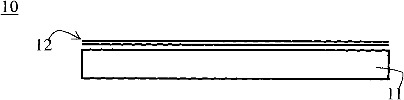
A backlight module and light source technology, which is applied to lighting devices, fixed lighting devices, components of lighting devices, etc., can solve problems such as the movement of the optical film 12, and achieve the effect of reducing the defect rate and solving the problem of movement.

Inactive Publication Date: 2010-03-17
DARWIN PRECISIONS SUZHOU CORP
View PDF0 Cites 8 Cited by
  • Summary
  • Abstract
  • Description
  • Claims
  • Application Information

AI Technical Summary

Problems solved by technology

Since the optical film 12 is only stacked on the light guide plate 11, the optical film 12 will move

Method used


Image

  • Backlight module and display device
  • Backlight module and display device
  • Backlight module and display device

Examples


Embodiment Construction

[0020] In order to have a further understanding of the purpose, structure, features, and functions of the present invention, the following detailed descriptions are provided in conjunction with the embodiments.

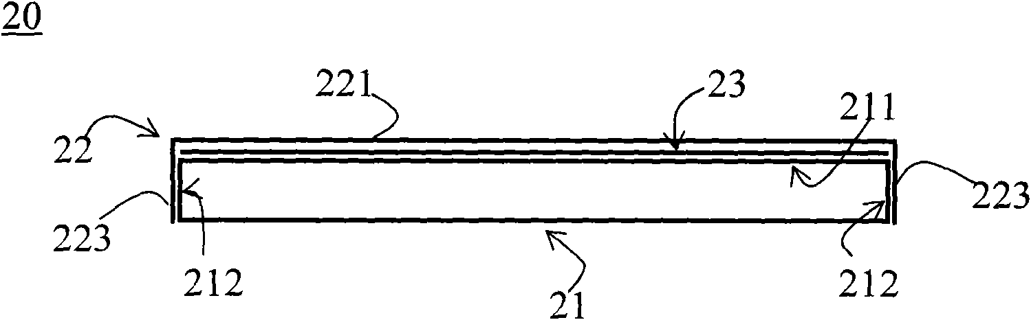
[0021] See figure 2 , figure 2 It is a schematic diagram of a backlight module 20 according to an embodiment of the present invention. The backlight module 20 includes a light guide plate 21 and a first optical film 22 , and the light guide plate 21 has a first end surface 211 and a second end surface 212 . The first optical film 22 includes an optical part 221 and an engaging part 223. The optical part 221 is arranged on the first end surface 211 of the light guide plate 21, and the engaging part 223 is arranged on the second end surface 212 of the light guide plate 21 to limit the first The optical film 22 moves. In this embodiment, the engaging portion 223 has a first segment and a second segment, and the optical portion 221 is located between the first segmen...


PUM


Abstract

The invention relates to a backlight module and a display device, wherein the backlight module comprises a light guide plate and a first optical film, the light guide plate has a first end face and asecond end face, the first optical film comprises an optical part and a clamping part, the optical part is arranged on the first end face of the light guide plate, and the clamping part is arranged onthe second end face of the light guide plate for limiting movement of the first optical film. The backlight module and the display device can effectively solve the problem that the optical film movesin the backlight module so as to reduce fraction defective of the display device.

Description

technical field [0001] The present invention relates to a backlight module and a display device, in particular to a backlight module capable of preventing optical film from moving and a display device using the backlight module. Background technique [0002] At present, flat panel display technology has been widely used in various electronic products such as computer monitors, televisions, notebook computers, mobile phones, and digital cameras due to its advantages of thinness, lightness, power saving, and low radiation. Taking a liquid crystal display as an example, since the liquid crystal unit itself does not emit light, a backlight module is required to provide a surface light source for the liquid crystal display device. The light guide plate in the backlight module is used to guide the transmission direction of the light beam emitted by the light source, and convert the point light source or linear light source into a surface light source before emitting it. The optic...

Claims


Application Information

Patent Timeline
Patent Type & Authority Applications(China)
IPC IPC(8): F21S8/00F21V5/00F21V8/00F21V17/10G02F1/13357
Inventor 何戌来
Owner DARWIN PRECISIONS SUZHOU CORP
Why Eureka
Try Eureka