Fan-out circuit and display panel

A fan-out line and display unit technology, applied in nonlinear optics, static indicators, optics, etc., can solve problems such as impedance differences, and achieve the effect of improving quality and uniform signal transmission quality

Active Publication Date: 2010-03-17
AU OPTRONICS CORP
View PDF4 Cites 30 Cited by
  • Summary
  • Abstract
  • Description
  • Claims
  • Application Information

AI Technical Summary

Problems solved by technology

In other words, there is still a significant impedance difference between the outermost wire 142a and the central wire 142b in the same fan-out line 140

Method used


Image

  • Fan-out circuit and display panel
  • Fan-out circuit and display panel
  • Fan-out circuit and display panel

Examples


Embodiment Construction

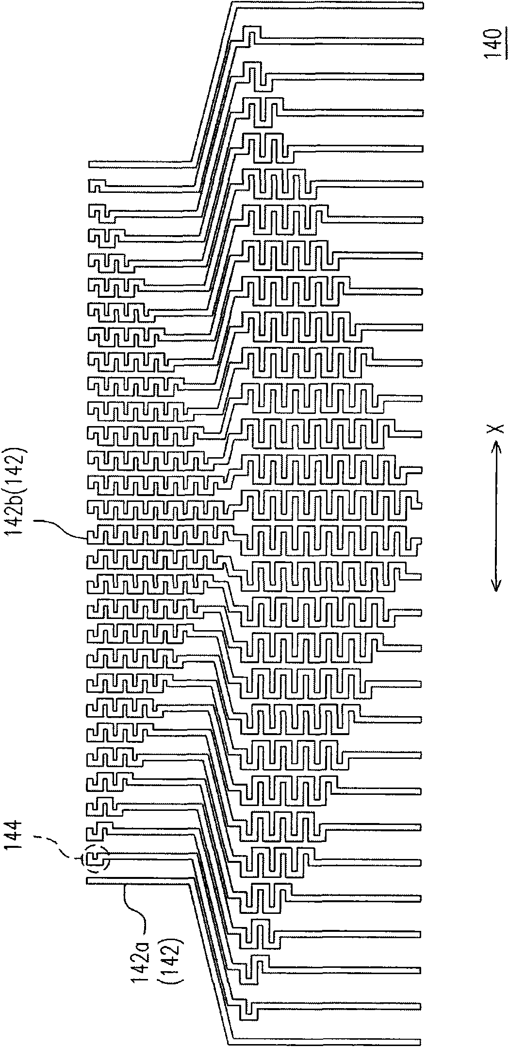
[0039] Figure 2A It is a schematic diagram of a fan-out circuit according to an embodiment of the present invention. Please refer to Figure 2A , the fan-out circuit 200 of this embodiment includes a plurality of fan-out wires 210 , wherein the fan-out wires 210 are electrically insulated from each other. Each fan-out wire 210 includes a first winding portion 212 and an extension portion 214 . The first winding portion 212 has a chip bonding end 212a and a first connecting end 212b, wherein the distance between any two adjacent chip bonding ends 212a is P1, and P1 is a positive number. The extension part 214 has a first end 214a and a second end 214b, wherein the first end 214a is connected to the first connection end 212b, wherein the distance between any two adjacent second ends 214b is P1', and P1'> P1. In the fan-out wire 210, a portion of the first winding portion 212 has a ladder shaped pattern L, that is, a portion of the first winding portion 212 may have a ladder...


PUM


Abstract

The invention discloses a fan-out circuit comprising a plurality of fan-out wires which are mutually electrically insulated, wherein each fan-out wire comprises a first winding part, an extension partand a second winding part; the first winding part is provided with a chip abutting end and a first connecting end, and the space between every two adjacent chip abutting ends is P1; the second winding part is provided with a second connecting end and a signal wire connecting end, and the second connecting end is connected with the first connecting end through the extension part; in addition, thespace between every two adjacent signal wire connecting ends is P2, and P2 is greater than P1; and in the fan-out wires, some of the first winding parts are provided with a staircase-shaped pattern. The invention also discloses a display panel containing the fan-out circuit.

Description

technical field [0001] The present invention relates to a fan-out circuit and a display panel, and in particular to a fan-out circuit and a display panel with small impedance differences. Background technique [0002] Liquid crystal display panels have the advantages of high image quality, small size, light weight, low voltage drive, low power consumption, and wide application range. Therefore, they have replaced cathode ray tubes (Cathode Ray Tube, CRT) and become the mainstream of the new generation of display devices. A traditional liquid crystal display panel is composed of a color filter substrate with a color filter layer, a thin film transistor array substrate (TFT Array Substrate), and a liquid crystal layer arranged between the two substrates. [0003] Figure 1A It is shown as an existing liquid crystal display panel. Please refer to Figure 1A , the known liquid crystal display panel 100 can be divided into an active area (active area) 102 and a peripheral circui...

Claims


Application Information

Patent Timeline
Patent Type & Authority Applications(China)
IPC IPC(8): G02F1/133
CPCG02F1/1345
Inventor 郑耕全
Owner AU OPTRONICS CORP
Why Eureka
Try Eureka