Power supply circuit, image forming device, power panel and processing unit

A processing unit and power supply technology, applied to the electrical recording process using the charge pattern, the equipment of the electric recording process using the charge pattern, and the electrography, etc., can solve the problems of contact surface wear and poor contact, and achieve easy loading and unloading , the effect of preventing poor contact

Inactive Publication Date: 2010-03-17
RICOH KK
View PDF2 Cites 14 Cited by
  • Summary
  • Abstract
  • Description
  • Claims
  • Application Information

AI Technical Summary

Problems solved by technology

[0009] However, when the power supply circuit is formed by crimping such a leaf spring-shaped connecting member, accuracy in positional relationship between the processing unit 301, the power board 302, and the connecting member 304 is required. In addition, because the connecting member 304 is in the shape of a leaf spring, and the contact surface will be worn due to friction, which will also cause poor contact
[0010] Also, in this configuration, since the places where the processing unit 301, the power supply board 302, and the connecting member 304 are installed are limited, it also becomes a constraint on the mechanical design.

Method used


Image

  • Power supply circuit, image forming device, power panel and processing unit
  • Power supply circuit, image forming device, power panel and processing unit
  • Power supply circuit, image forming device, power panel and processing unit

Examples


Embodiment Construction

[0036] Hereinafter, the best mode for carrying out the present invention will be described with reference to the drawings. In addition, those skilled in the art can change and modify the present invention within the scope of the claims to easily form other embodiments. These changes and modifications are included in the scope of the claims. The following description is the best mode of the present invention. examples, and do not limit the scope of its claims.

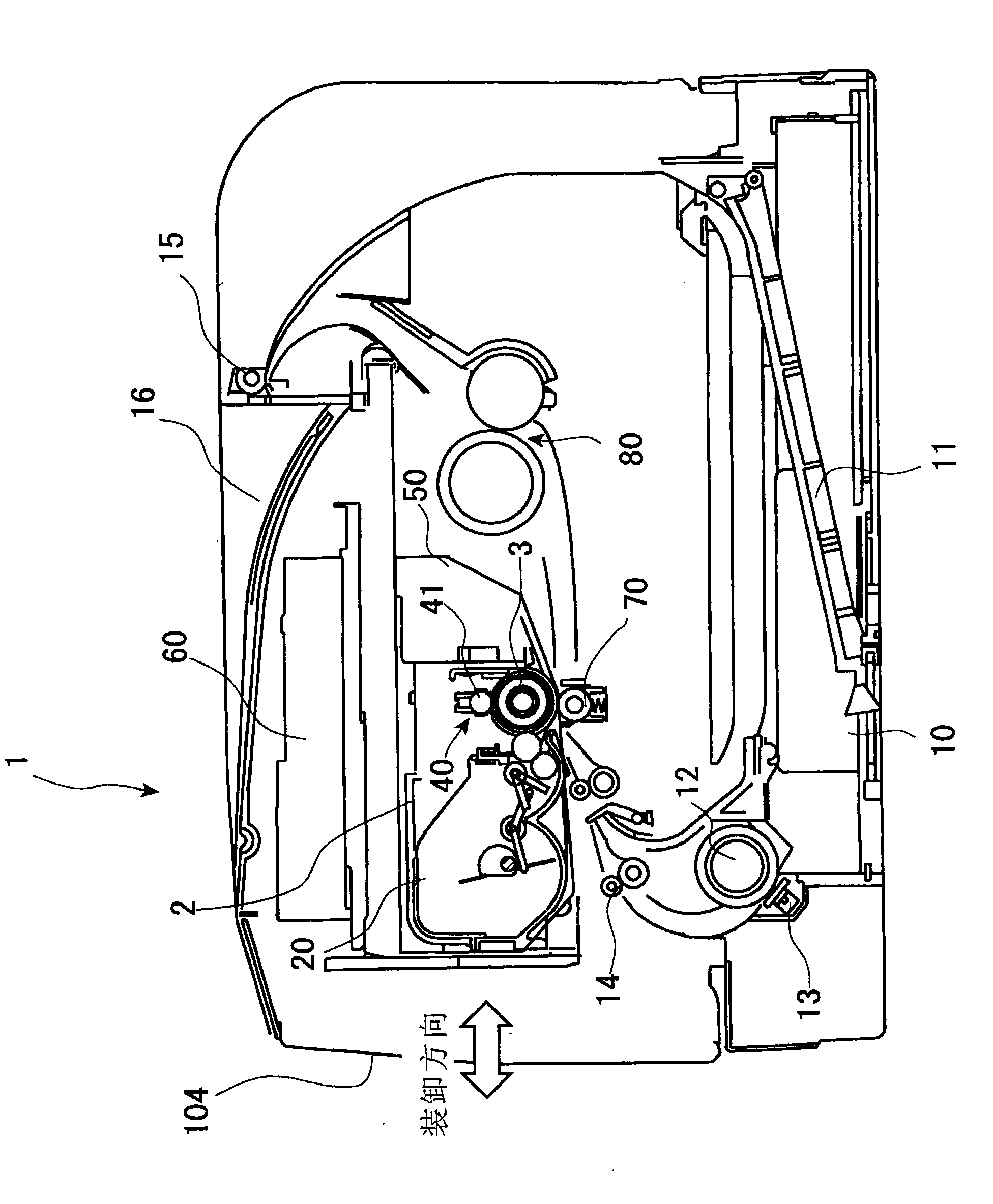
[0037] figure 1 It is a block diagram of an image forming apparatus including the developing device of the present invention.

[0038] Such as figure 1 As shown, a processing unit 2 is provided in the center of the image forming apparatus 1 , and a paper feeding assembly 10 having a paper feeding cassette 11 is disposed below the processing unit 2 . The processing unit 2 can be attached and detached by opening the outer cover 104 of the image forming apparatus 1 on the processing unit 2 side.

[0039] In the proce...


PUM


Abstract

The invention provides a power panel with convenient assembly and disassembly, and further provides an image forming device not capable of generating poor connection among the power panel, an image carrier, a current-carrying device, a processing unit and the like. The method is characterized in that: a contact terminal (4) is arranged on a lateral surface of the processing unit (2); a contact terminal (92) on the body side is arranged at a position contacted with the contact terminal (4); the contact terminal (92) on the body side can be positioned in a displacing way along a direction vertical to a moving direction of the processing unit (2), and retreats in the direction vertical to the moving direction corresponding to the stress when moving from the processing unit (2) by attaching to the processing unit through a spring (93); and when the processing unit (2) is being mounted, the processing unit is connected with the contact terminal (4) on the processing unit side in a pressingway.

Description

technical field [0001] The present invention relates to power supply circuits for copiers, printers, facsimile machines, etc., image forming apparatuses, power boards, and processing units. In more detail, it relates to a processing unit or a power board that can be installed and detached from the image forming device, and is electrically connected to the image forming device body. Background technique [0002] In an image forming apparatus in which a detachable processing unit can be attached, when the processing unit is installed, necessary power is supplied from the main body to drive the processing unit. [0003] Therefore, in the image forming apparatus, a power supply board from which power is supplied to the processing unit is provided. [0004] The power supply board is usually detachably installed in the main body of the image forming apparatus, the power supply circuit from the power supply board to the processing unit is formed in the main body, and the circuit i...

Claims


Application Information

Patent Timeline
Patent Type & Authority Applications(China)
IPC IPC(8): H01R13/24H01R4/48G03G15/00B41J2/385
Inventor 都何军
Owner RICOH KK
Why Eureka
Try Eureka