Connector

A technology for connectors and contact parts, applied in the direction of connection, multi-conductor connectors, conductive connections, etc., can solve the problems of difficult to stabilize the friction force between the conductor and the first jaw, poor contact between the conductor and the power supply terminal, etc., and achieve labor saving , the effect of preventing poor contact

Active Publication Date: 2012-03-28
PANASONIC INTELLECTUAL PROPERTY MANAGEMENT CO LTD
View PDF16 Cites 13 Cited by
  • Summary
  • Abstract
  • Description
  • Claims
  • Application Information

AI Technical Summary

Problems solved by technology

Therefore, it is difficult to stabilize the frictional force between the conductor and the first jaw, and as a result, poor contact between the conductor and the power supply terminal may occur.

Method used


Image

  • Connector
  • Connector
  • Connector

Examples


Embodiment Construction

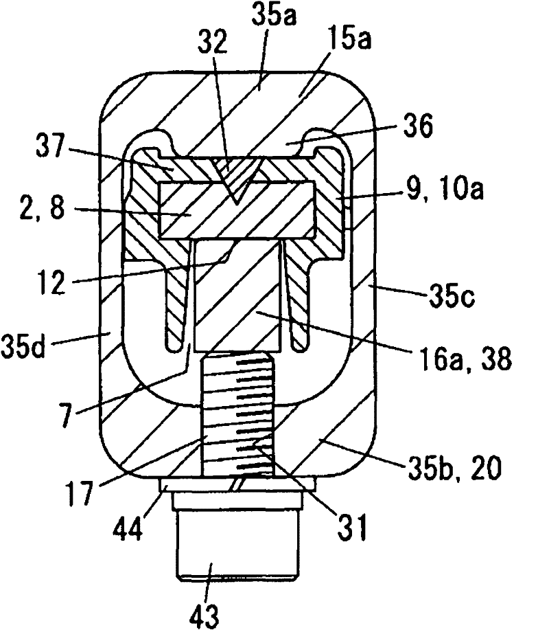
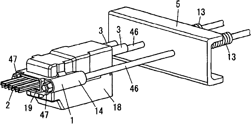
[0032] The present invention is described based on the drawings. In addition, the following reference Figure 15 The situation described. In addition, in the description of each structure below, the direction of the construction state is used as a reference, and the insertion direction of the connector 1 in the longitudinal direction of the overhead insulated wire 2 is described as the rear side, and the opposite direction is described as the front side. The width direction of the overhead insulated wire 2 will be described as the left-right direction (horizontal direction).

[0033] The connector 1 of this embodiment is as figure 2 As shown, the overhead insulated wire 2 is connected to the power line 3 made of cables, and the mobile equipment 6 (refer to Figure 15 ) used in the power supply system for power supply.

[0034] Such as Figure 15 As shown, the overhead insulated wire 2 supplies power to the mobile equipment 6 composed of a hoisting crane through the current ...


PUM


Abstract

The present invention provides a connector which can reduce labor amount in processing for stripping out conductor of overhead insulated wire and can prevent inferior contact between terminals and the conductor of the overhead insulated wire. Terminals (16a-16c) which can connect electric wires (3) are provided with contact parts (38). The contact parts contact with an exposed surface (12) which is exposed from a slot opening (7) of sheath parts (10a-10c) of the overhead insulated wire (2). The connector is provided with a pressing component (17) which directly presses the contact parts (38) from an opposite side of the conductor (8) to the side of the conductor (8).

Description

technical field [0001] The present invention relates to a connector for electrically connecting overhead insulated wires with power lines. Background technique [0002] In the past, such as Figure 15 As shown, an overhead insulated wire 2 is used to supply power to mobile equipment 6 such as a hoisting crane through a power collector 11 . A general overhead insulated wire 2 has a structure in which a conductor is provided in a groove of a sheath portion, the sheath is formed on a resin insulator, and the conductor is exposed from the opening of the groove of the sheath portion. [0003] Reference numeral 1' denotes a connector for electrically connecting an overhead insulated wire to a power line 3 on the primary side, and as this connector, for example, a structure shown in Patent Document 1 is known. In this connector, the conductor is stripped by cutting off the insulation on the end of the overhead insulated wire using a drilling tool, etc., and the stripped conductor ...

Claims


Application Information

Patent Timeline
Patent Type & Authority Applications(China)
IPC IPC(8): H01R11/03H01R4/36
CPCB60M1/12H01R4/00H01R41/00
Inventor 楠户雅佳
Owner PANASONIC INTELLECTUAL PROPERTY MANAGEMENT CO LTD
Why Eureka
Try Eureka