Lateral crystallization reduction jar for vacuum metal smelting

A technology of vacuum smelting and reduction tanks, which is applied in the field of vacuum smelting reduction tanks for smelting metal magnesium or calcium. It can solve the problems of elongated production cycle, cumbersome crystallizer procedures, and high labor intensity of workers, so as to reduce tempering combustion losses, The effect of shortening the stoppage and refueling time and improving work safety

Inactive Publication Date: 2010-03-24
辛卫亚
View PDF0 Cites 6 Cited by
  • Summary
  • Abstract
  • Description
  • Claims
  • Application Information

AI Technical Summary

Problems solved by technology

[0005] The advantage of using the Pidgeon method to smelt magnesium is that the method is simple and has been used for a long time, but its shortcomings include high energy consumption and environmental pollution, as well as:
[0006] 1. The pellets are squeezed against the reduction furnace, which greatly hinders the circulation of magnesium vapor, resulting in incomplete precipitation of metal magnesium, prolonging the reduction time, and resulting in the inability to increase the ratio of magnesium to material, resulting in further waste of energy. Reduced production efficiency;
[0007] 2. The crystallizer is set on the top of the reduction furnace, and the reduction tank must be removed before the crystallizer can be taken out for replacement. It takes a long time to stop production and refuel, thus prolonging the production cycle and increasing the cost of heating the reduction tank; in addition, the output of magnesium The procedures for replacing the crystallizer are cumbersome, which also leads to high labor intensity for workers and many unsafe hazards;
[0008] 3. The crystallizer is set on the top of the reduction furnace, which is prone to tempering combustion loss

Method used


Image

  • Lateral crystallization reduction jar for vacuum metal smelting
  • Lateral crystallization reduction jar for vacuum metal smelting
  • Lateral crystallization reduction jar for vacuum metal smelting

Examples


Embodiment Construction

[0032] In order to better understand the structure and features of the present invention, the present invention will be described in detail below in combination with preferred embodiments and accompanying drawings. In order to make the structure of the present invention clearer, the actual scale relationship of the drawings may be changed during the drawing process, which should not be construed as a limitation to the patent application.

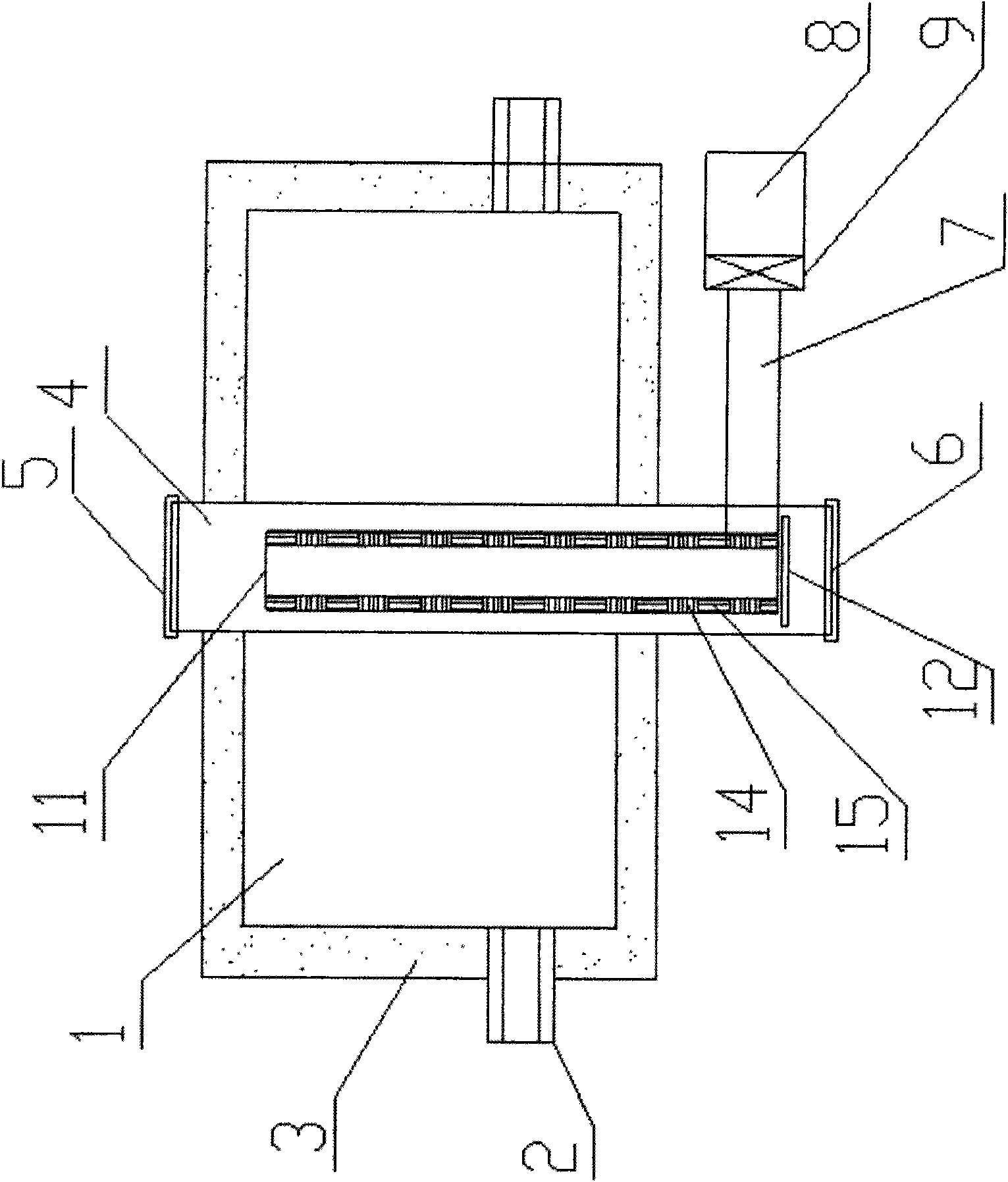
[0033] Such as figure 1 Shown is a schematic diagram of the structure of the side crystallization metal vacuum smelting reduction tank 4 of the present invention arranged in the reduction furnace 1. The reduction furnace 1 adopts regenerative combustion technology, and is provided with a furnace body 3 and a burner 2. All are prior art, need not repeat them. The reduction tank 4 is vertically arranged in the furnace body 3 of the reduction furnace 1 , and both ends extend out of the furnace body 3 . Wherein, the upper end of the reduction ...


PUM


Abstract

The invention provides a lateral crystallization reduction jar for vacuum metal smelting. The reduction jar is vertically placed in a reduction furnace body. The upper and lower ends of the reductionjar extend out of the furnace body. A draft tube is fixedly arranged in the reduction jar and is in a hollow shape. Gaps exist between the outer walls of the draft tube and the inner walls of the reduction jar and can be used for placing pellet materials. A plurality of pores which penetrate the wall thickness are arranged on the draft tube body to communicate the inside with the outside of the draft tube. A tubular flow guide device is arranged at the side of the upper end or the lower end of the reduction jar. One end of the flow guide device extends into the reduction jar while the other end thereof is communicated with a crystallizer. The reduction jar can accelerate the circulation velocity of magnesium vapor and shorten the reduction time. Removal of the crystallizer and feeding anddischarging in the reduction jar are carried out in a mutually independent manner, thus shortening the time of stopping production for reloading and increasing the working efficiency.

Description

technical field [0001] The invention relates to a metal vacuum smelting reduction tank, in particular to a vacuum smelting reduction tank for smelting metal magnesium or calcium. Background technique [0002] Some alkali metals and alkaline earth metals with high vapor pressure, such as chromium, chromium, magnesium, calcium, etc., can be prepared by metallothermic reduction of silicon, aluminum or their alloys under vacuum conditions. Among the metallothermal reduction preparation methods of magnesium, the silicothermal or aluminothermic metalthermal reduction principles are most widely used, but the reducing agent is mostly used in the form of ferrosilicon alloy, and the raw material to be reduced is mostly calcined dolomite. A wrought product of a mixture of magnesite and limestone can also be used. The use of ferrosilicon reducing agent, known as silicothermal magnesium smelting, is the most widely used. [0003] According to the different heating methods, the current ...

Claims


Application Information

Patent Timeline
Patent Type & Authority Applications(China)
IPC IPC(8): C22B5/16C22B26/20
Inventor 辛卫亚
Owner 辛卫亚
Why Eureka
Try Eureka