Cooling apparatus boiling and condensing refrigerant with a refrigerant vapor passage having a large cross sectional area

a technology of condensing refrigerant and refrigerant vapor passage, which is applied in the direction of insulated conductors, semiconductor/solid-state device details, cables, etc., can solve the problems of degrading achieve the effect of eliminating the degradation of the efficiency of the apparatus, convenient assembly and smooth circulation of the refrigeran

Inactive Publication Date: 2005-04-05
DENSO CORP
View PDF13 Cites 26 Cited by
  • Summary
  • Abstract
  • Description
  • Claims
  • Application Information

AI Technical Summary

Benefits of technology

In view of the drawbacks mentioned above, according to the invention, there is provided a cooling apparatus boiling and condensing refrigerant in which a malfunction of refrigerant circulation, caused by opposed flows between condensed refrigerant and refrigerant vapor, can be prevented and the degradation of the efficiency thereof can be eliminated. The other purpose of the invention is to provide the cooling apparatus boiling and condensing refrigerant in which the circulation of the refrigerant can be performed smoothly without increasing the size thereof and can be more easily assembled.
According to the constitution, the refrigerant vapor boiled and evaporated by receiving the heat from the heat-generating member is introduced in the tubes located within the boiling area through the opening portions of the intermediate plate adjacent to the heat radiating plate. As the opening portions of the intermediate plate can be increased according to the boiling area, the performance of the apparatus can be improved due to smooth circulation of the refrigerant and easy passage of the refrigerant vapor.

Problems solved by technology

Due to this, a malfunction of refrigerant circulation is caused and the efficiency of the apparatus is degraded.

Method used


Image

  • Cooling apparatus boiling and condensing refrigerant with a refrigerant vapor passage having a large cross sectional area
  • Cooling apparatus boiling and condensing refrigerant with a refrigerant vapor passage having a large cross sectional area
  • Cooling apparatus boiling and condensing refrigerant with a refrigerant vapor passage having a large cross sectional area

Examples


first embodiment

(The First Embodiment)

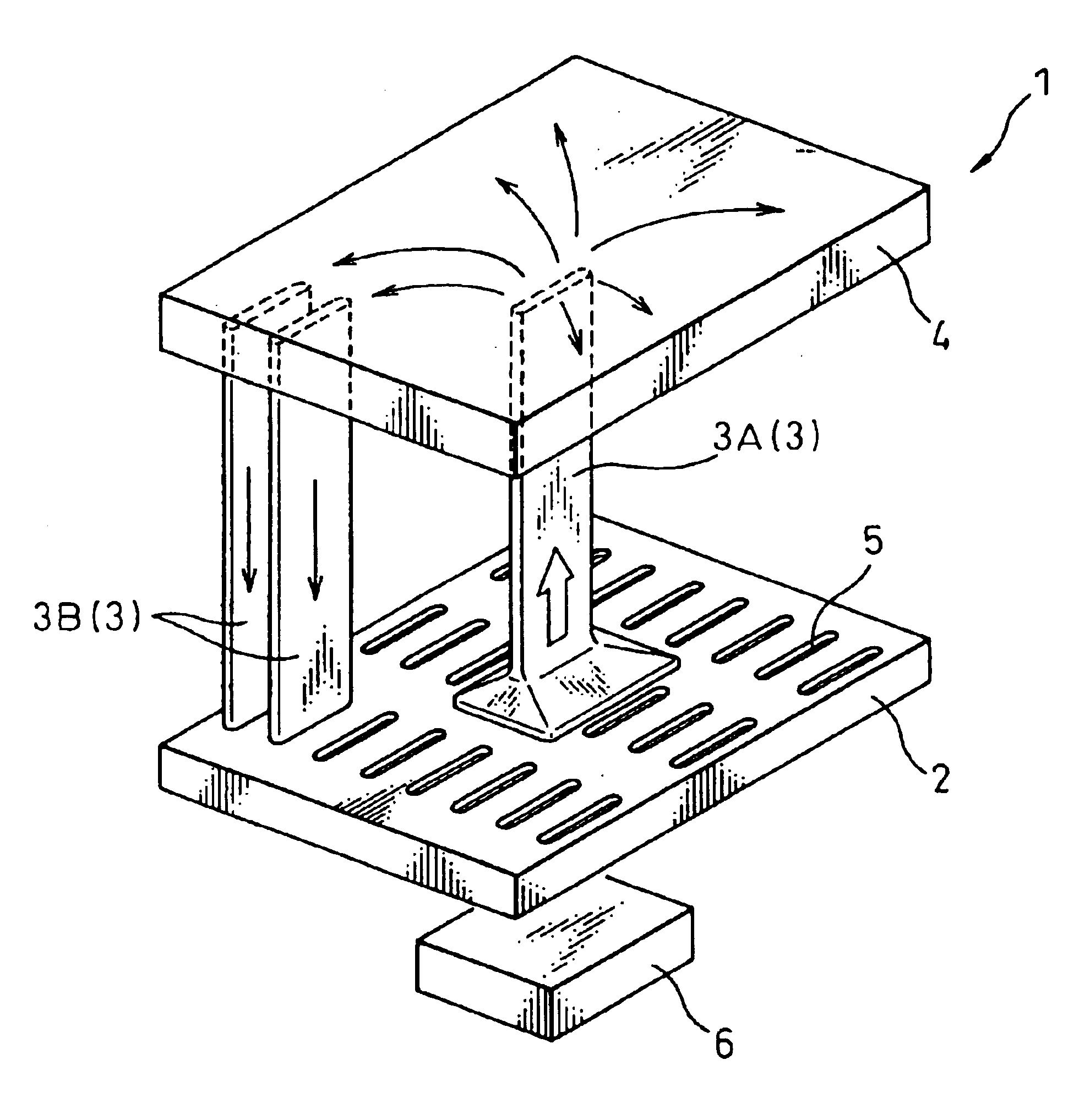
FIG. 1 is a perspective view of a cooling apparatus 1 boiling and condensing refrigerant.

The cooling apparatus 1 boiling and condensing refrigerant of the present embodiment is comprised of a refrigerant container 2 in which refrigerant is reserved, a plurality of tubes 3 (3A, 3B) which connect to the inside of the refrigerant container 2, and a header tank 4 by which a plurality of the tubes 3 are communicated; and is manufactured integrally, for example, by brazing in a vacuum.

As can be seen in FIG. 1, the refrigerant container 2 is in the form of a flat box in a vertical direction. A plurality of inserting holes 5 in which lower end portions of the tubes 3 are inserted are provided on the upper surface of the refrigerant container 2. At a center portion of a bottom surface of the refrigerant container 2, a heat-generating member 6 in which heat-generating elements such as a semiconductor device, etc. are built in is attached thereto by screws, etc. A portion...

second embodiment

(The Second Embodiment)

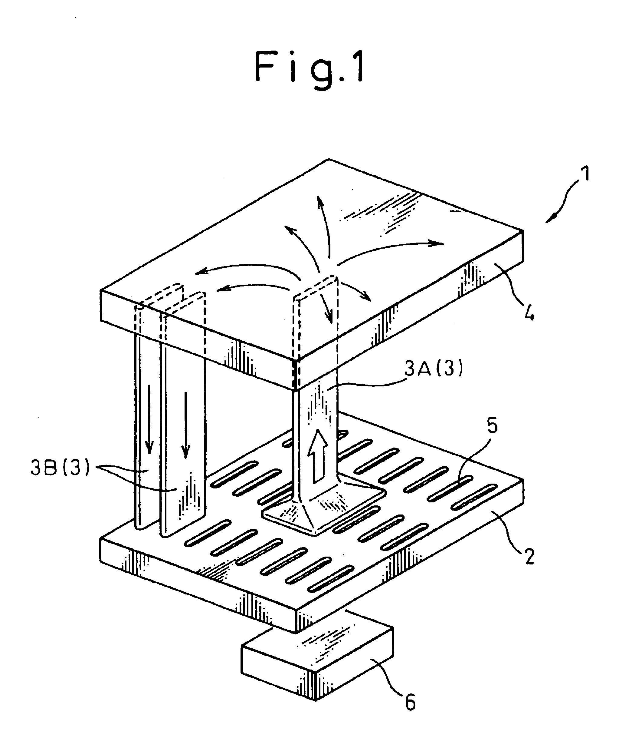
FIG. 2 is a perspective view of a cooling apparatus 1 boiling and condensing refrigerant. As shown in FIG. 2, in this embodiment a tube 3A is located within the boiling area and has a larger passage cross section than other tubes 3B, over the entirely of the length thereof, by way of example. According to the constitution, as the flow resistance against the refrigerant vapor upon passing through the tube 3A can be low, the refrigerant vapor can be easily introduced into the tube 3A. Thus, the performance of the apparatus can be high by smooth circulation of the refrigerant.

third embodiment

(The Third Embodiment)

FIG. 3 is a perspective view of a cooling apparatus 1 boiling and condensing refrigerant. As shown in FIG. 3, in this embodiment a multilayered refrigerant container 2 and a multilayered header tank 4 are provided, by way of example. The refrigerant container 2 is formed, for example, by superimposing four plates 7 (7A-7D), as shown in FIGS. 4A through 4D. Each of the plates 7 is obtained by punching a plate such as an aluminum plate, a stainless plate or the like using a press die. The plates 7 are comprised of a heat receiving plate 7A having a heat-generating member 6 secured to the surface thereof, a heat radiating plate 7B having tubes 3 mounted to the surface thereof, and two (or more than two) intermediate plates 7C, 7D held between the plates 7A and 7B.

As shown in FIG. 4A, a plurality of inserting holes 5 for inserting the end portions of the tubes 3 are formed in the heat radiating plate 7B. Note that the inserting hole 5a which opens into the boiling ...


PUM


Abstract

Tubes 3 are provided substantially upright on an upper surface of a refrigerant container 2 by inserting lower end portions thereof into inserting holes 5 of the refrigerant container 2. The tube 3A, differed from the tubes 3B, has a trumpet shape which is suddenly increased in its passage cross section towards the lower end opening portion. Thus, most of refrigerant vapor boiled and evaporated in the refrigerant container 2 can be collectively introduced into the tube 3A located within the boiling area. The refrigerant vapor entered a header tank 4 from the tube 3A is diffused in the header tank 4, and is introduced into the tubes 3B located out of the boiling area. The condensate produced by cooling the refrigerant vapor upon passing through the tubes 3B can be circulated into the refrigerant container 2.

Description

BACKGROUND OF THE INVENTION1. Field of the InventionThis invention relates to a cooling apparatus boiling and condensing refrigerant which cools a heat-generating member by heat transfer with boiling of a refrigerant.2. Description of the Related ArtA conventional cooling apparatus boiling and condensing refrigerant is indicated in FIG. 7, by way of example.This cooling apparatus boiling and condensing refrigerant is comprised of a refrigerant container 100 which reserves refrigerant liquid, a pair of headers 110, 120 each of which is connected to the refrigerant container 100, a plurality of tubes 130 provided between the header 110 and the header 120, and heat radiating fins 140 for radiating heat transferred from the tubes 130 into the air. A heat-generating element 150 is attached to a bottom surface of the refrigerant container 100.A separating wall 160 which determines a direction of circulation of the refrigerant is provided in the refrigerant container 100. Accordingly, as i...

Claims


Application Information

Patent Timeline
Patent Type & Authority Patents(United States)
IPC IPC(8): F28D15/02
CPCF28D15/0266F28F13/08F28F9/026
Inventor OHARA, TAKAHIDE
Owner DENSO CORP
Why Eureka
Try Eureka