Light source of projector

A projector and light source technology, which is applied in the field of projector light sources, can solve problems such as brightness drop, screen shaking, and reduced service life, and achieve the effects of not being easy to attenuate brightness, improve output quality, and reduce use costs

Inactive Publication Date: 2010-03-24
沈立
View PDF0 Cites 3 Cited by
  • Summary
  • Abstract
  • Description
  • Claims
  • Application Information

AI Technical Summary

Problems solved by technology

like image 3 As shown, in the optical path of a projector using a non-imaging system light source, the increase in the length of the plasma light-emitting arc will increase the spot area at the focal point C2 in the two-dimensional direction, thereby reducing the available luminous flux of the subsequent system and causing the output efficiency , which is mainly manifested as a decrease in brightness on the projection screen
[0005] In addition, the spatial position of the plasma light arc between the electrodes will change with time. When the light emitting area of ​​the light arc deviates from the focus of the reflector cup, the brightness of the screen will decrease; due to the spatial position of the light arc in the non-imaging system Changes are very sensitive. When the above-mentioned space position of the light-emitting arc changes with a high frequency, it will also manifest as obvious screen shake, such as Figure 4 shown
[0006] Furthermore, the cooling of the wick in the traditional reflector is non-uniform, so the end of the wick inside the reflector tends to fail prematurely due to high temperature and reduce the service life
This is because in the traditional working mode, the high temperature at the top of the bulb causes crystallization on the inner wall of the top of the bulb, which leads to the failure of the wick, such as Figure 5 shown
In addition, the cooling method is usually air-cooled. If the cooling air directly cools the top of the bulb, the working temperature inside the wick will be too low, which will also cause the wick to fail to start or affect the halogenation reduction reaction inside the wick bulb, thereby reducing the service life.

Method used


Image

  • Light source of projector
  • Light source of projector
  • Light source of projector

Examples


Embodiment Construction

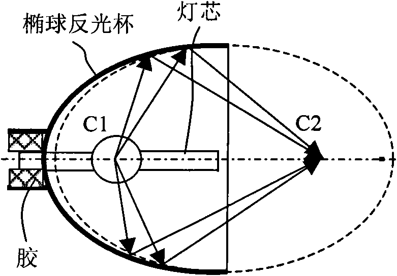
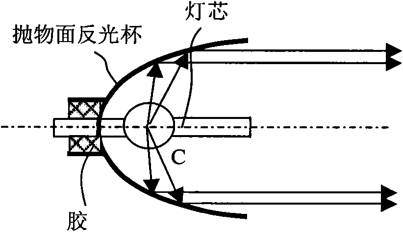
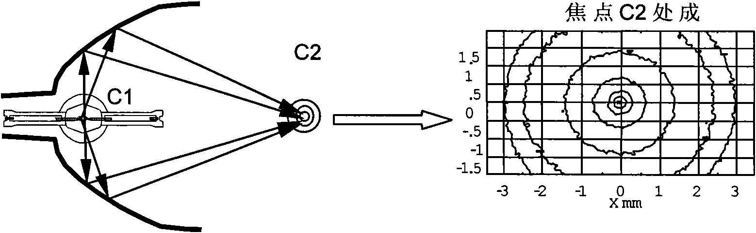
[0018] Such as Figure 6 As shown, a projector light source includes two reflectors, wherein the primary reflector 1 is a spherical or approximately spherical reflector, the secondary reflector 2 is an ellipsoidal reflector, and the front end of the primary reflector has an opening 3 . A wick 4 is also included, the axis of the wick 4 is not perpendicular to the optical axis of the reflective cup, and the light-emitting area between the electrodes of the wick is located on the focal point F1 of the secondary reflective cup 2 . The axis of the wick can form an included angle within ±20° with the horizontal plane. The wick 4 is detachably installed on the wick support 5 such that the wick 4 is located between the primary reflector 1 and the secondary reflector 2 , and the wick 4 is installed symmetrically with respect to the optical axis of the reflector. Reflector material can be metal, boride glass or ceramic material.

[0019] Such as Figure 7 As shown, when the wick 4 o...


PUM


Abstract

The invention provides a light source of a projector to prolong service life of the light source, improve output quality of light and have easy replacement of lampwick of the projector. The inventioncomprises two light reflecting cups and a lampwick, wherein a first light reflecting cup is a sphere or sphere-like light reflecting body, a second light reflecting cup is an ellipsoid reflecting body; and the front end of the first light reflecting cup is arranged with an opening; and the axis of the lampwick is not perpendicular to the optical axis of the light reflecting cup, a luminous sectorbetween electrodes of the lampwick is located at focus F1 of the second light reflecting cup, the axis of the lampwick forms an included angle within +/-20 degrees with the horizontal plane, the dismountable lampwick is arranged on a lampwick rack to enable the lampwick to be located between the first light reflecting cup and the second light reflecting cup, and the lampwick is installed symmetrically with the optical axis of the light reflecting cup. The invention realizes easy replacement of lampwicks, avoids unnecessary waste of light reflecting cups and light racks and reduces use cost.

Description

technical field [0001] The invention relates to a light source for a projector, in particular to a plug-and-play projector light source with a replaceable wick. Background technique [0002] At present, the commonly used projector light sources are mainly divided into two types according to the type of their reflectors, namely ellipsoid lamps and parabolic lamps. What they have in common is that the wick as a luminous body is fixed at a specific position in the reflector, usually so that the plasma light-emitting area in the wick coincides with the focus of the reflector to obtain optimal use of light energy; in addition, in the manufacturing process The common point is that the wick is fixed at the end of the reflector cup by glue and cannot be disassembled. The difference between the two is that the light of the ellipsoidal cup starts from the focal point C1 of the reflective cup, and is concentrated and output at another focal point C2 at the front end of the reflective ...

Claims


Application Information

Patent Timeline
Patent Type & Authority Applications(China)
IPC IPC(8): G03B21/20F21V3/02F21V3/04
Inventor 沈立
Owner 沈立
Why Eureka
Try Eureka