
Gas combustion type driving tool

A technology for driving tools and gas, which is applied in the direction of nailing tools and manufacturing tools, and can solve the problems of increasing the overall weight

Active Publication Date: 2010-03-24
MAX CO LTD
View PDF9 Cites 3 Cited by
  • Summary
  • Abstract
  • Description
  • Claims
  • Application Information

AI Technical Summary

Problems solved by technology

Therefore, there is a problem that the overall weight increases

Method used


Image

  • Gas combustion type driving tool
  • Gas combustion type driving tool
  • Gas combustion type driving tool

Examples


Embodiment Construction

[0041] Hereinafter, a nail driver will be described as a gas combustion chamber driving tool according to the present invention.

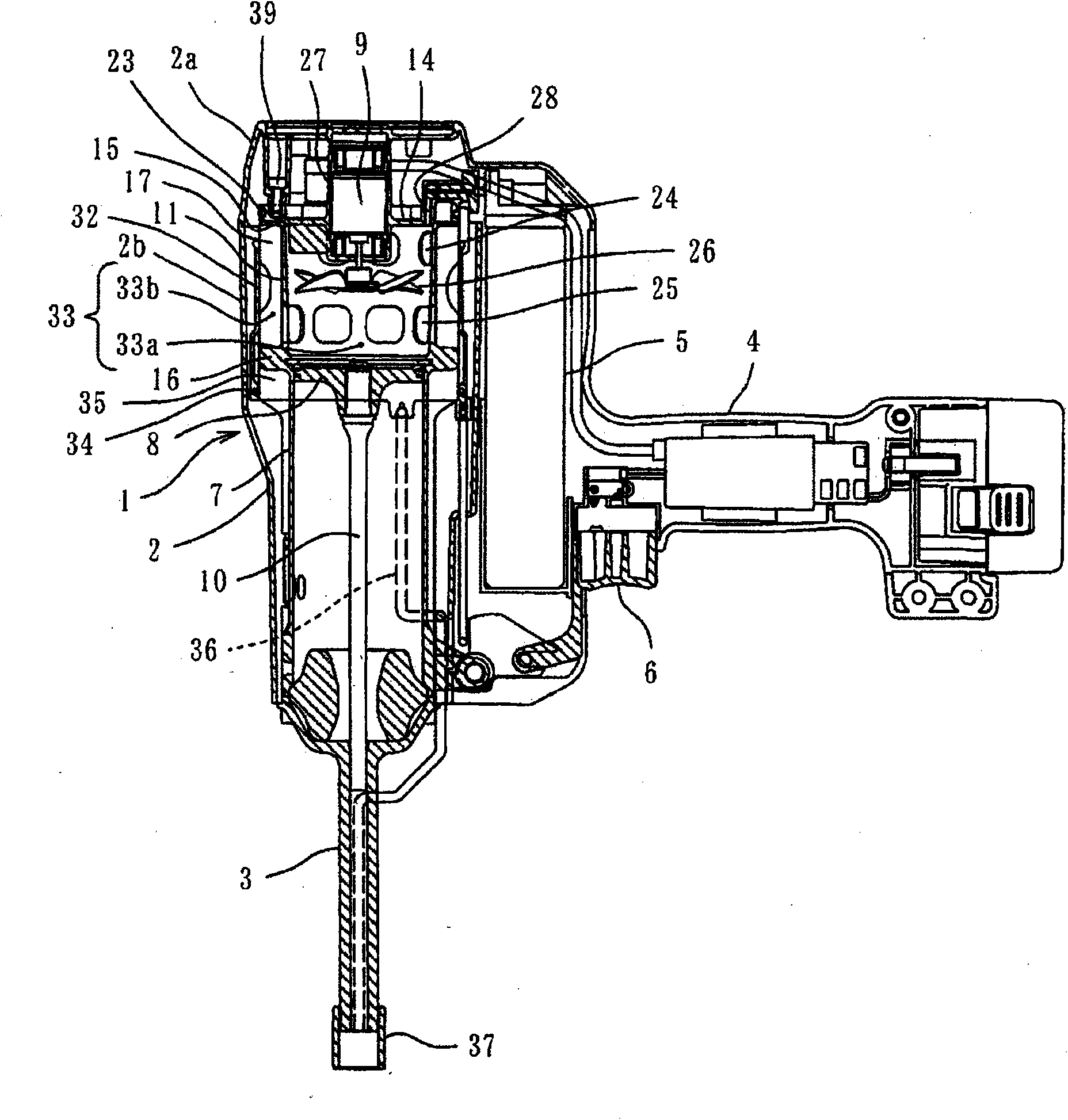
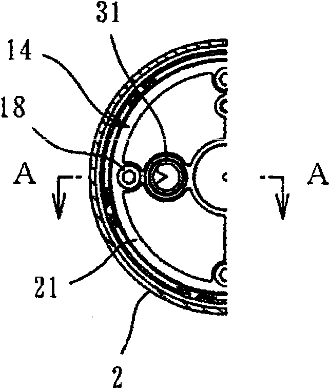
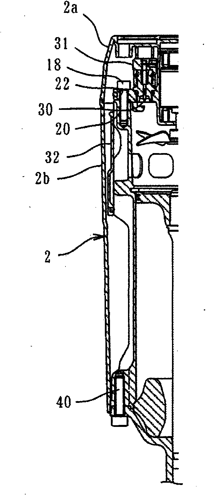
[0042] exist Figure 1 to Figure 4 In , reference numeral 1 denotes a tool body of a gas combustion driving tool (nail driver). This tool main body 1 is provided with combustion chamber and piston-cylinder mechanism in the inside of main body cover 2, is provided with the machine head 3 that is used for driving nail under the tool main body 1, is connected with handle 4 on the tool main body 1, on the machine head A staple cartridge (not shown) is connected to the part 3 , and a gas container 5 is detachably provided on the handle 4 side of the tool body 1 . Reference numeral 6 denotes a trigger.

[0043] In the piston-cylinder mechanism, a piston 8 is slidably accommodated in a cylinder 7 , and a driver 10 is integrally coupled below the piston 8 .

[0044] A cylindrical connecting wall 11 is provided as a connecting portion on the upper extens...


PUM


Abstract

The invention provides a gas combustion type driving tool. A piston (8) is slidably received in a cylinder (7), and a tubular movable sleeve (32) is movably placed above a cylinder (7), between the cylinder (7) and a cylinder head (14). A connection section is provided above the cylinder (7), and the cylinder (7) and the cylinder head (14) are connected to each other by the connection section. The outer side of the connection section is covered by a body cover (2).

Description

technical field [0001] The present invention relates to an improvement in the main body structure of a gas combustion type driving tool. Background technique [0002] In general, in a gas combustion type driving tool, the cylinder, the piston, and the cylinder head arranged above the cylinder that constitute the driving mechanism of the fastener are formed of metal such as aluminum, and the cylinder and the cylinder head are fixed to a synthetic resin. on the subject. That is, the cylinder head is fixed to the upper end of the main body, and the cylinder is fixed to the middle and lower parts of the main body. The movable sleeve is arranged between the cylinder and the cylinder head so as to be movable up and down, and a combustion chamber is formed inside it, and the combustion chamber is opened and closed by the movable sleeve (see Patent Document 1). [0003] Patent Document 1: Japanese Patent Laid-Open No. 2005-329533 [0004] In the gas combustion driving tool descri...

Claims


Application Information

Patent Timeline
Patent Type & Authority Applications(China)
IPC IPC(8): B25C1/08
CPCB25C1/08B25C1/18
Inventor 田中宏司
Owner MAX CO LTD
Learn More