
Pump unit with a main pump and a charging pump with a variable pump capacity

A technology of pump unit and booster pump, which is applied in the direction of pump, pump control, multi-cylinder pump, etc., to achieve the effect of adjusting performance

Active Publication Date: 2010-03-24
ROBERT BOSCH GMBH
View PDF3 Cites 1 Cited by
  • Summary
  • Abstract
  • Description
  • Claims
  • Application Information

AI Technical Summary

Problems solved by technology

[0004] A disadvantage of the known system comprising two hydraulic pumps connected in series is that the adjustment of the pumping flow of the first pump supplying the second pump with pressure medium is not carried out as a function of the pressure acting on the input side of the second pump

Method used


Image

  • Pump unit with a main pump and a charging pump with a variable pump capacity
  • Pump unit with a main pump and a charging pump with a variable pump capacity

Examples


Embodiment Construction

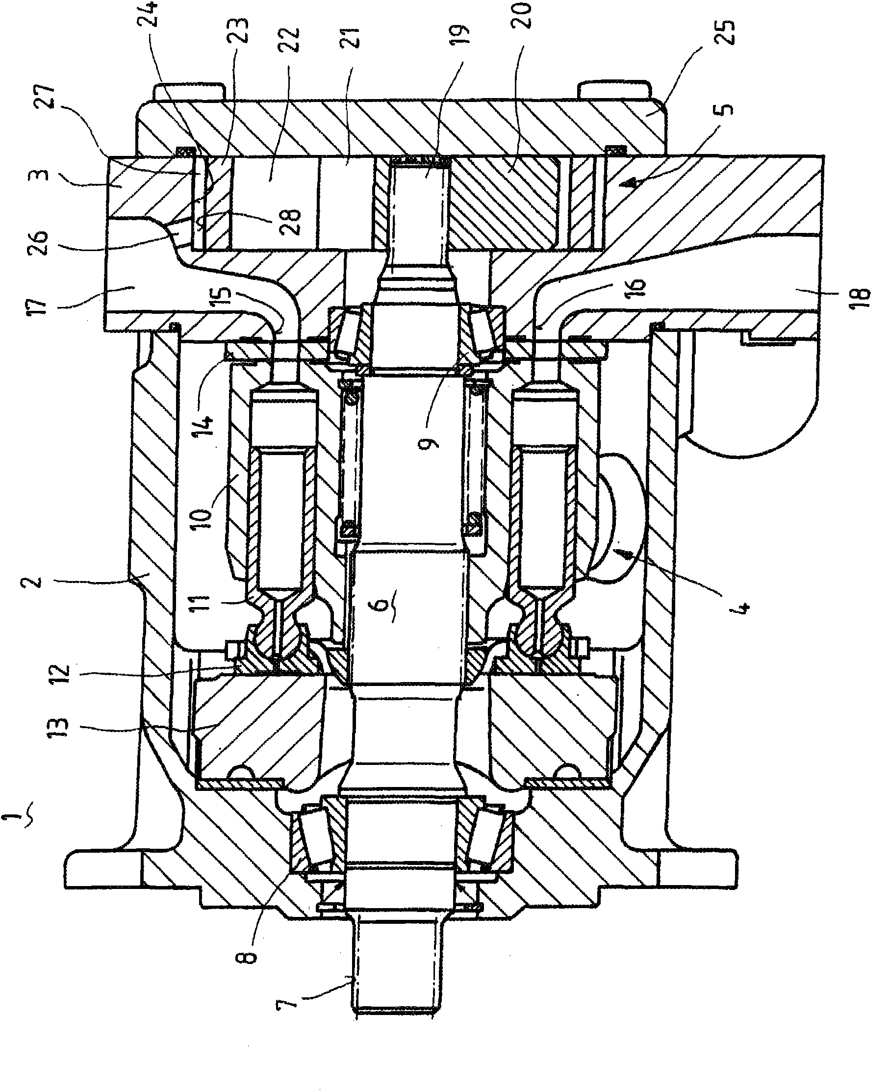
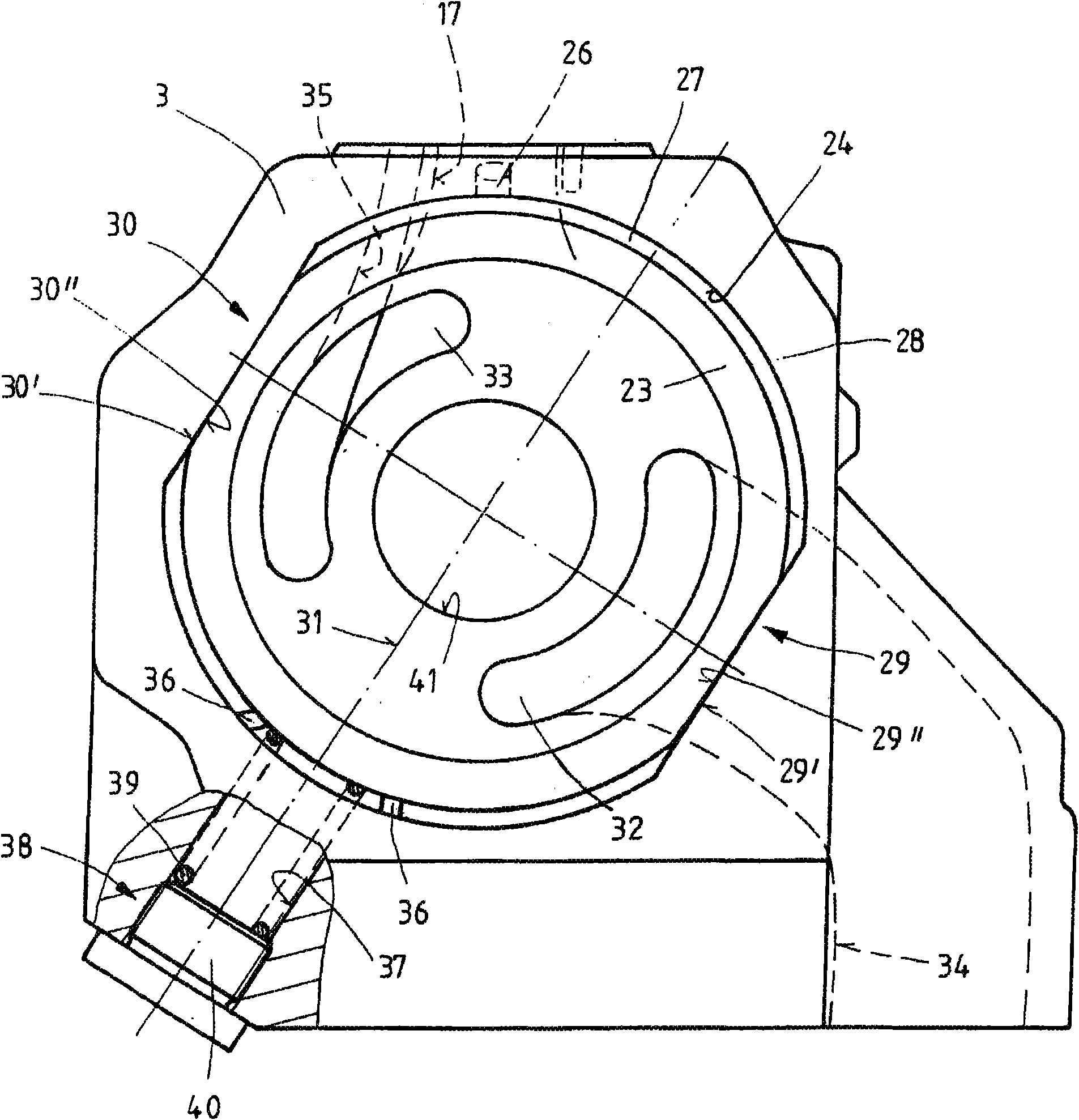
[0021] exist figure 1 A preferred embodiment of a pump unit 1 according to the invention is shown in , comprising a housing comprising a pot-shaped housing part 2 and a further housing part closing the pot-shaped housing part 2 . The other housing part is in the shape of the connecting plate 3 . A main pump 4 is arranged in the pot-shaped housing part 2 . The booster pump 5 is arranged on the side of the connecting plate 3 remote from the pot-shaped housing part 2 .

[0022] In the exemplary embodiment shown, the main pump 4 and the booster pump 5 in the form of axial piston machines are driven via a common drive shaft 6 . The drive shaft 6 has a shaft end protruding from the pot-shaped housing part 2 in the bottom region. A tooth portion 7 is formed on this shaft end of the drive shaft 6 . The toothing 7 serves to couple the drive shaft 6 in a rotationally fixed manner to a torque generator.

[0023] The common drive shaft 6 is rotatably supported in the housing of the p...


PUM


Abstract

The invention relates to a pump unit (1) with a main pump (4) and a charging pump (5) with a variable pump capacity. A lifting ring (23) is provided for varying the capacity of the charging pump (5).A regulating power, which depends on the inlet pressure of the main pump (4), acts on the lifting ring (23).

Description

technical field [0001] The invention relates to a pump unit comprising a main pump and a booster pump with adjustable pumping flow. Background technique [0002] A hydraulic system comprising a main pump and a booster pump is known from DE 10045118 A1. The proposed hydraulic system has two pumps in a series arrangement, the pumping flow of each of the two pumps is adjustable. The pumping side of the booster pump is connected to the inlet side of the main pump, and the booster pump can be adjusted by an adjustment mechanism. For this purpose, a control or regulating device is provided which acts on the regulating mechanism of the booster pump. [0003] A system comprising two pumps connected in series is also disclosed from GB2150981A. The booster pump draws pressure medium from the sump volume and sends it to the main pump through the connecting line. Both the main pump and the booster pump are designed to be adjustable and each have a control unit. There is an electron...

Claims


Application Information

Patent Timeline
Patent Type & Authority Applications(China)
IPC IPC(8): F04B23/10F04B49/12F04C14/02
CPCF04B2205/06F04B23/106F04C14/02F04B2205/01F04B49/12F04B1/07F04B23/12
Inventor R·C·希勒S·默茨M·J·朱格G·U·莫恩
Owner ROBERT BOSCH GMBH
Learn More