Control unit for automatic transmission

A technology of automatic transmission and control unit, which is applied in the directions of transmission control, control device, and components with teeth, etc., can solve the problems of increasing the number of parts, increasing the size of the SBW-ECU110, and increasing the manufacturing cost.

Inactive Publication Date: 2010-03-24
AISIN AW CO LTD
View PDF1 Cites 2 Cited by
  • Summary
  • Abstract
  • Description
  • Claims
  • Application Information

AI Technical Summary

Problems solved by technology

[0003] However, in the above-mentioned conventional shift-by-wire device, etc., the actuator 130, the SBW-ECU 110, and the AT-ECU 120 are housed in different housings, and therefore it is necessary to provide separate vehicle loading spaces, which increases the size of the entire device.
In addition, in the SBW-ECU 110, since the driving current of the actuator 130 is to flow through the inner layer pattern of the printed circuit board, the size of the printed circuit board is increased, and the size of the SBW-ECU 110 is also increased.
In addition, since the actuator 130, the SBW-ECU 110, and the AT-ECU 120 are housed in different housings, and the SBW-ECU 110 and the AT-ECU 120 have similar circuit functions such as a power supply and a CAN interface, the number of parts increases, resulting in Manufacturing cost surge

Method used


Image

  • Control unit for automatic transmission
  • Control unit for automatic transmission
  • Control unit for automatic transmission

Examples


Embodiment Construction

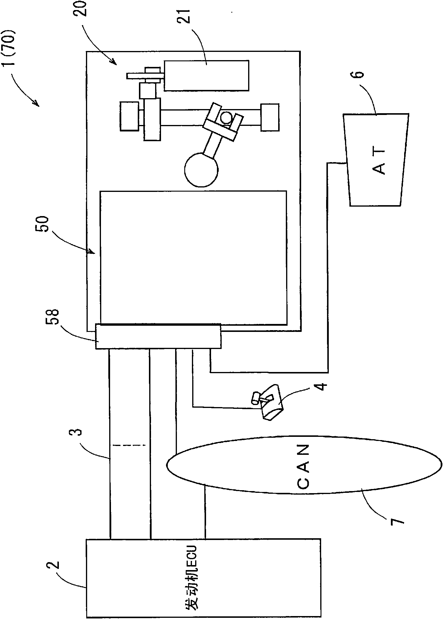
[0032] Hereinafter, an embodiment in which the automatic transmission control unit of the present invention is embodied will be described with reference to the drawings. Such as figure 1 As shown, the automatic transmission control unit 1 of the embodiment is connected to the engine ECU 2 by the wire harness 3 through the connector 58 , and is also connected to the shift lever 4 and the automatic transmission 6 . Here, the engine ECU 2 controls the engine, and the driver selects and operates the shift lever 4 to determine a selected gear, so that the driving gear of the automatic transmission 6 is set to a desired gear. In addition, the automatic transmission 6 can automatically switch the gear ratio according to the speed of the vehicle and the number of revolutions of the engine. The automatic transmission control unit 1 and the engine ECU 2 are connected through a connection mechanism such as a vehicle communication system CAN (Controller Area Network) 7 , and can communi...


PUM


Abstract

A control unit for a vehicle automatic transmission is small sized and can be produced at low cost. The control unit has an actuator (20) for switching between drive ranges of the transmission (6), ashift-by-wire control circuit (53) for controlling the actuator (20) based on a range selected by a driver, and an automatic transmission control circuit (56) for controlling various kinds of valves of a hydraulic control device of the automatic transmission (6). The elements described above are received in one case (10, 11, 12) and mounted on the automatic transmission (6).

Description

technical field [0001] The invention relates to an automatic transmission control unit for switching driving gears of an automatic transmission for vehicles. Background technique [0002] In recent years, such as Figure 8 As shown, a shift-by-wire (shift-by-wire) device is loaded in the vehicle, and the shift-by-wire device has: an actuator (actuator) 130 for switching the driving range of the automatic transmission 140 for the vehicle; A shift-by-wire control circuit (hereinafter referred to as "SBW-ECU") 110 of the actuator 130 is controlled by a specified gear selected by the driver. In addition, an automatic transmission control circuit (hereinafter referred to as “AT-ECU”) 120 for controlling various valves of a hydraulic control device of an automatic transmission 140 is also mounted on the vehicle. The actuator 130, SBW-ECU110 and AT-ECU120 are housed in different boxes respectively, and the SBW-ECU110 and AT-ECU120 communicate with the engine ECU100 for controlling...

Claims


Application Information

Patent Timeline
Patent Type & Authority Applications(China)
IPC IPC(8): F16H61/28B60K17/06
CPCF16H2061/326F16H2061/2884F16H61/32Y10T74/2003
Inventor 伊藤悦申田中玄昌
Owner AISIN AW CO LTD
Why Eureka
Try Eureka