Supercharge Your Innovation With Domain-Expert AI Agents!

Optical scanning actuator

A technology for actuators and optical scanning, which is applied in optics, instruments, optical components, etc., can solve problems such as scanning errors, durability problems, and obstacles to widening the scanning angle, and achieve the effect of wide-angle durability

Inactive Publication Date: 2010-03-24
NHK SPRING CO LTD
View PDF1 Cites 1 Cited by
  • Summary
  • Abstract
  • Description
  • Claims
  • Application Information

AI Technical Summary

Problems solved by technology

[0007] However, in the prior art described above, as the swing angle of the reflection mirror 36 from the original position becomes larger, the influence of the bending of the plate springs 34a, 34b becomes significant, and the movable part retreats slightly toward the fixed member 33, and the coils 37a, The inner surface of 37b is in contact with the yoke 38
Therefore, an error occurs in the scanning of the wide-angle area with a large swing angle from the origin position, which becomes an obstacle to widening the scanning angle.
In addition, due to the contact between the inner surfaces of the coils 37a, 37b and the yoke 38 in the wide-angle area, the above-mentioned members may be damaged, and there may be a problem in the durability of the device.

Method used


Image

  • Optical scanning actuator
  • Optical scanning actuator
  • Optical scanning actuator

Examples


Embodiment Construction

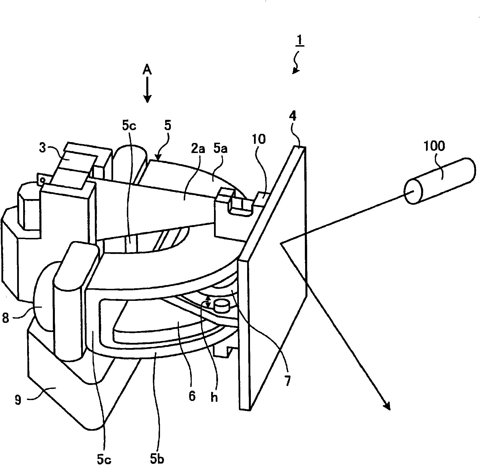
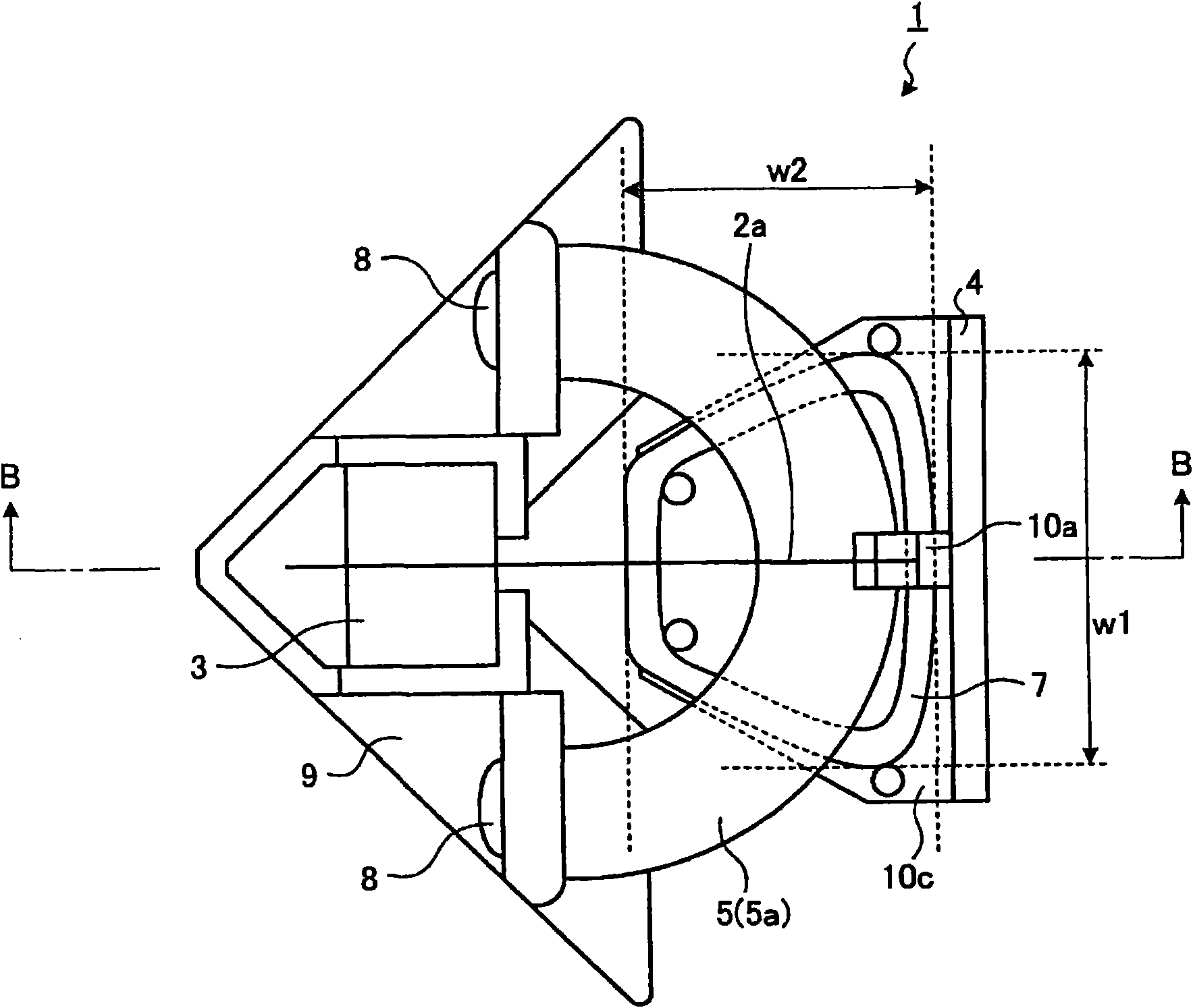
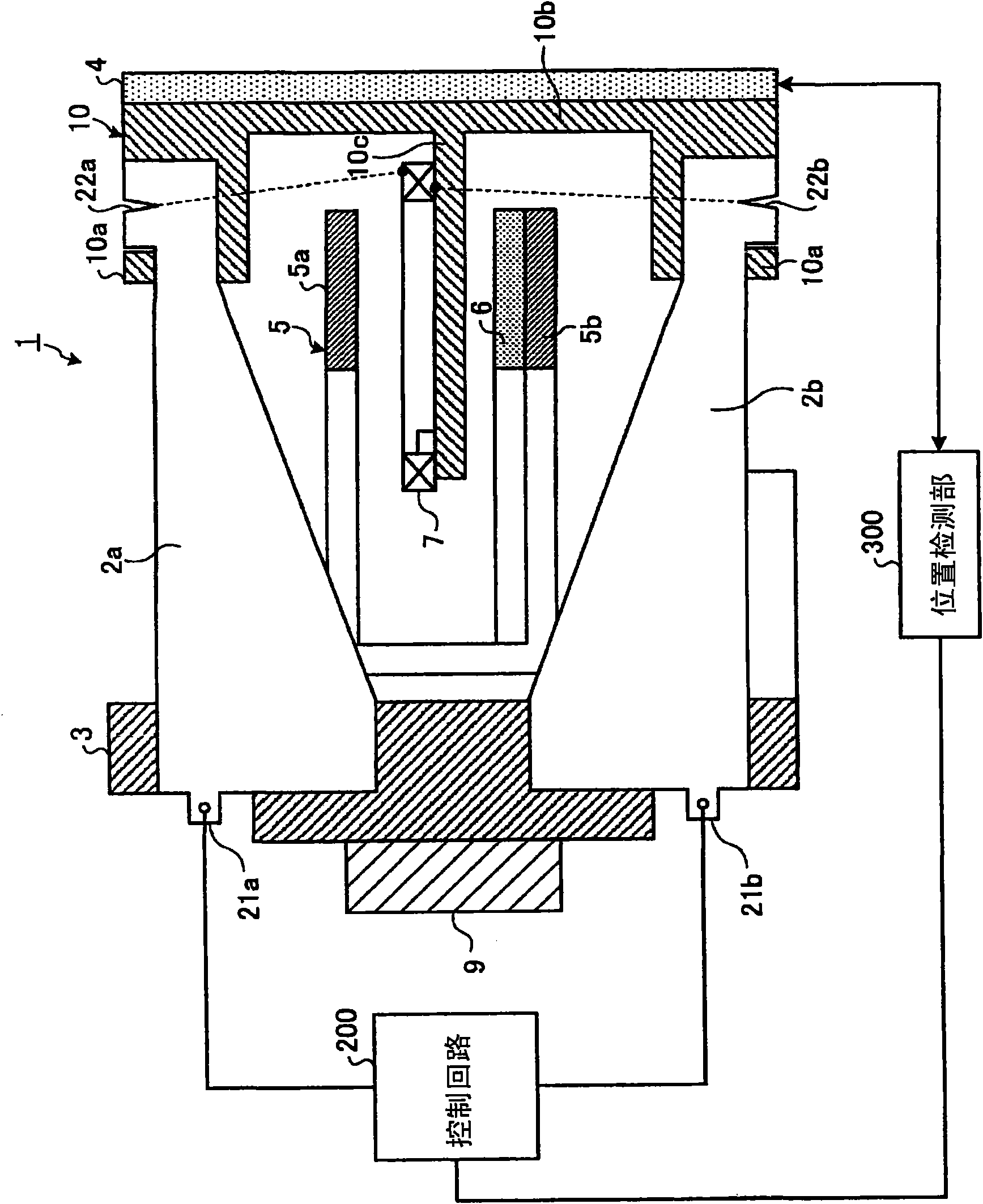
[0046] Hereinafter, specific embodiments of the present invention (hereinafter referred to as "embodiments") will be described with reference to the drawings. figure 1 It is a perspective view showing the configuration of an optical scanning actuator according to one embodiment of the present invention. in addition, figure 2 Yes figure 1 The top view in the direction of the arrow A. image 3 Yes figure 2 Partial sectional view of B-B line.

[0047] Figure 1 ~ Figure 3 The shown optical scanning actuator 1 has: two leaf springs 2a, 2b; a fixing member 3 for fixing the base ends of the leaf springs 2a, 2b; An optical element that emits incident light and emits the reflected light; a yoke 5 and a magnet 6 that form a closed magnetic circuit; a coil 7 disposed in the gap between the yoke 5 and the magnet 6; a base member 9 that remains fixed The member 3 is fixed to the yoke 5 via the screw member 8; the frame member 10 constitutes a movable part that can move together ...


PUM


Abstract

To provide an optical scanning actuator that is capable of realizing widening of a light scanning angle and is excellent in durability, the optical scanning actuator includes a movable unit that supports an optical element, a plurality of leaf springs having a thin plate shape with one end portion being fixed and another end portion being attached to the movable unit, and an electromagnetic driving unit including a magnet, a yoke laminated on the magnet to form a closed magnetic circuit together with the magnet, and a coil held by the movable unit. The coil is positioned in a gap between the magnet and the yoke such that opening plane of the coil is substantially orthogonal to a laminating direction of the magnet and the yoke. The movable unit is driven by an electromagnetic force appliedto the coil.

Description

technical field [0001] The present invention relates to an actuator for scanning light that scans emitted light. Background technique [0002] Conventionally, scanning laser radar devices, laser scanners, laser printers, laser markers, object monitoring devices, and the like are known as devices that use scanning devices such as laser light. Among the above-mentioned devices, as an optical scanning actuator used in a scanning laser radar device for preventing vehicle impact, it is known that a movable mirror is swung or rotated by a motor, and the light emitted by the laser light source is directed toward the A technique in which a movable mirror is irradiated and the reflected light is scanned as scanning light (for example, refer to Patent Document 1). [0003] Image 6 It is a perspective view showing the structure of a conventional optical scanning actuator. In the optical scanning actuator 31 shown in this figure, the base ends of a pair of leaf springs 34a, 34b arran...

Claims


Application Information

Patent Timeline
IPC IPC(8): G02B26/10H04N1/113
CPCG02B26/105H04N1/1135H04N2201/02495H04N2201/02477H02K41/0358H04N2201/0246
Inventor 重松良平今村州平田贵史
Owner NHK SPRING CO LTD
Features
  • R&D
  • Intellectual Property
  • Life Sciences
  • Materials
  • Tech Scout
  • Unparalleled Data Quality
  • Higher Quality Content
  • 60% Fewer Hallucinations
Learn More