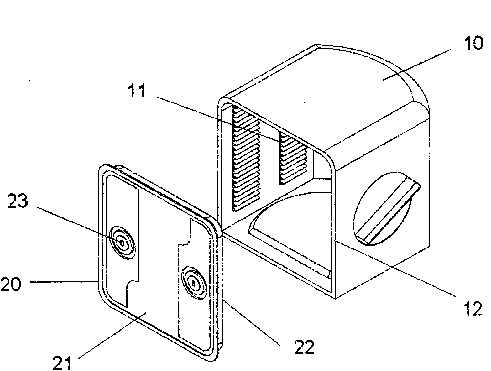
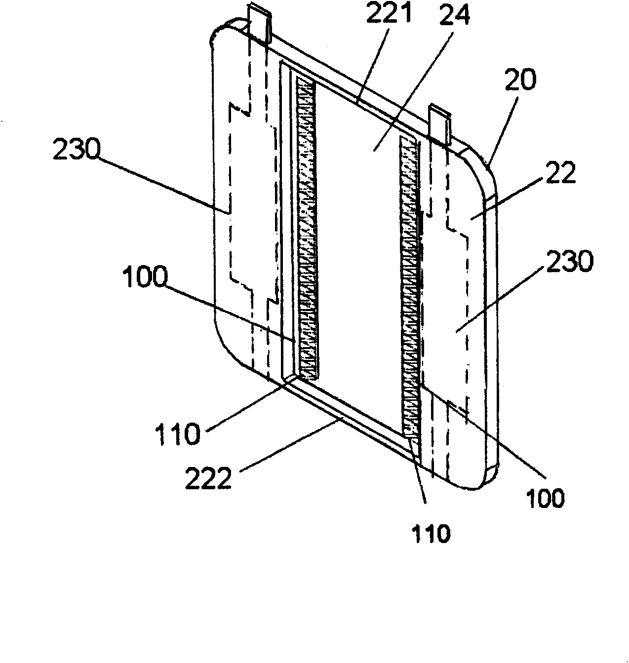
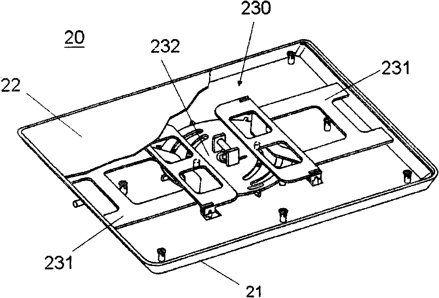
Front open type wafer box with latch and airtight structure
A front-opening wafer box, air-tight structure technology, applied in electrical components, semiconductor/solid-state device manufacturing, circuits, etc., can solve the problem that the box body 10 cannot be stuck, the box body 10 and the door body 20 cannot be closed, and Issues such as increasing the manufacturing cost of front-opening wafer cassettes
- Summary
- Abstract
- Description
- Claims
- Application Information
AI Technical Summary
Problems solved by technology
Method used
Image

Examples
Embodiment Construction
[0043] Please refer to Figure 5 , is a top view of a latch structure 60 of a door body 20 of the FOUP according to the present invention. Such as Figure 5 As shown, a pair of latch structures 60 are included between the outer surface and the inner surface of the door body 20, wherein each latch structure 60 is composed of an elliptical cam 62, a pair of sliding devices 64 in contact with the two ends of the elliptical cam 62, at least one The pulley 66 is disposed between the outer surface and the inner surface of the door body 20 and is embedded in the slide groove 642 of the sliding device 64 and at least one positioning elastic piece 68 integrally connected with the sliding device 64 . Next, please refer to Image 6 ,yes Figure 5 The enlarged schematic diagram of the contact end of the elliptical cam 62 and the sliding device 64 in FIG. Such as Image 6 As shown, in a preferred embodiment of the present invention, a positioning pulley 644 can be configured at the co...
PUM
 Abstract
Description
Claims
Application Information