Motor rotor

A technology of motor rotor and rotating shaft, which is applied to the magnetic circuit rotating parts, magnetic circuit shape/style/structure, etc., can solve the problems of poor combination stability, complicated assembly of components, inconvenience, etc., to improve the convenience of assembly, The effect of reducing the complexity of the overall structure and reducing the cost of materials

Inactive Publication Date: 2010-03-31
SUNONWEALTH ELECTRIC MACHINE IND
View PDF2 Cites 4 Cited by
  • Summary
  • Abstract
  • Description
  • Claims
  • Application Information

AI Technical Summary

Problems solved by technology

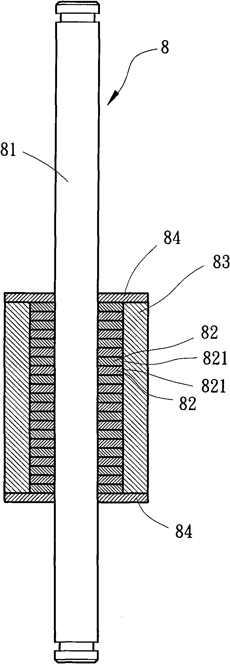
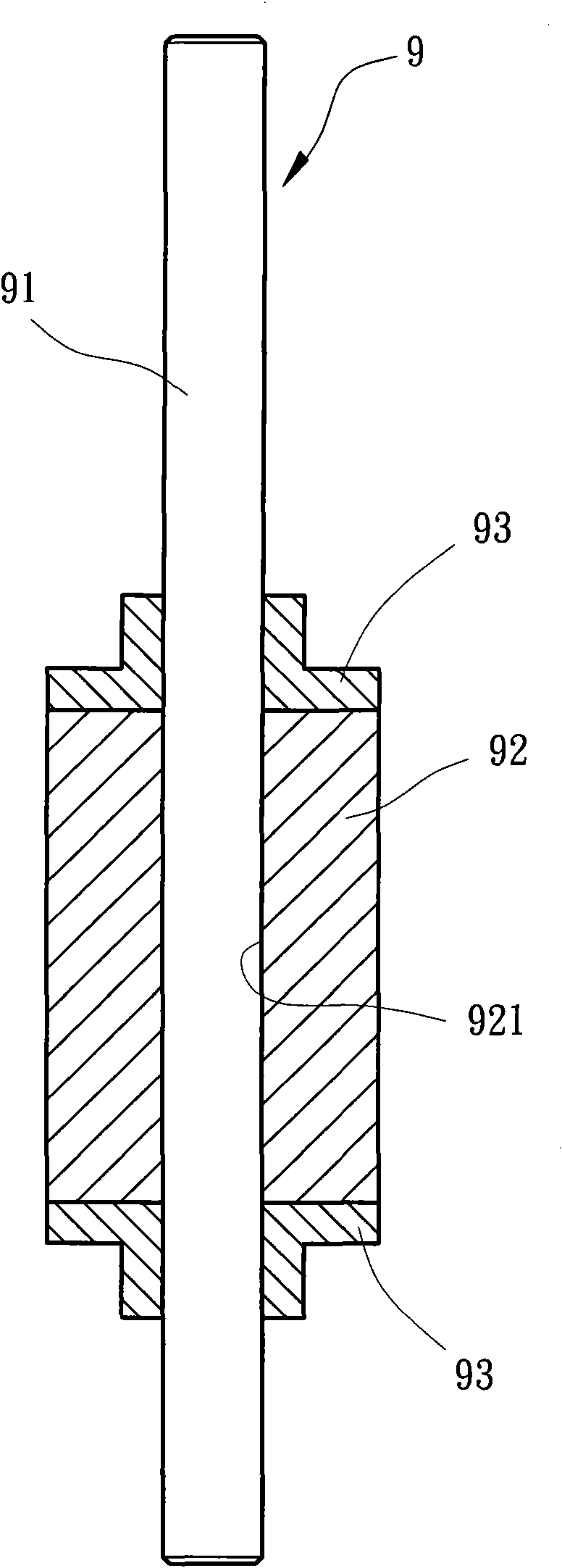
However, in terms of the research and development direction of the current motor structure, it has generally been developed and designed towards the direction of convenient assembly and a more streamlined structure. Therefore, the aforementioned second type of existing rotor 8 and the t

Method used


Image

  • Motor rotor
  • Motor rotor
  • Motor rotor

Examples


Embodiment approach

[0037] Please refer to Figure 4 , 5 and Figure 6Shown is the first implementation state of the rotor 1 of the present invention, the rotor 1 includes a rotating shaft 10 and a plastic magnet 20 . The outer peripheral surface of the rotating shaft 10 has a positioning portion 11, the positioning portion 11 forms several axial grooves 111 on the outer peripheral surface of the rotating shaft 10, and each axial groove 111 has a distance from each other, so that By utilizing the design of each of the axial grooves 111 , the cross section of the positioning portion 11 in the radial direction is non-circular. In this way, when the plastic magnet 20 is coated on the outer peripheral surface of the rotating shaft 10 by injection molding, the inner peripheral wall formed by the plastic magnet 20 and each axial groove 111 of the positioning part 11 can be formed. The engaged state ensures that the plastic magnet 20 will not rotate arbitrarily relative to the rotating shaft 10 , and...


PUM


Abstract

The invention relates to a motor rotor comprising a rotation shaft and a plasticity magnet. The periphery surface of the rotation shaft is provided with a positioning part which is provided with a cross section in the radial direction, wherein the cross section is in a non right round shape; the plasticity magnet coats the periphery surface of the rotation shaft in an injection molding pattern, and the inner walls formed by the plasticity are mutually clipped and combined with the positioning part. By adopting the structure, the plasticity magnet can be ensured not to drop from the rotation shaft so as to have a stable combination effect and simultaneously reduce integral structural complexity as well as improve the assembly convenience.

Description

technical field [0001] The invention relates to a motor rotor, in particular to a rotor structure of an inner rotor motor. Background technique [0002] Currently, the common motor structures in the market can be roughly divided into outer rotor motors and inner rotor motors. Compared with inner rotor motors, outer rotor motors generally have problems such as poorer rotation stability. Therefore, under the premise that electronic products are generally developed and designed in the direction of high speed, functional integration and miniaturization, compared with external rotor motors, inner rotor motors can better meet the heat dissipation requirements of the aforementioned electronic products. [0003] Please refer to figure 1 As shown, the rotor 7 of the first type of conventional inner rotor motor generally includes a rotating shaft 71 and a magnet 72 , and the center of the magnet 72 passes through a shaft hole 721 , and the shaft hole 721 allows the rotating shaft 71 ...

Claims


Application Information

Patent Timeline
IPC IPC(8): H02K1/27H02K1/28
Inventor 洪银树尹佐国
Owner SUNONWEALTH ELECTRIC MACHINE IND
Why Eureka
Try Eureka