Shot-blasting machine

A technology of shot blasting device and lifting device, which is applied to the processing device of used abrasives, abrasive jetting machine tools, abrasives, etc., and can solve the problems of saving space and other disadvantages

Active Publication Date: 2010-03-31
SINTOKOGIO LTD
View PDF2 Cites 15 Cited by
  • Summary
  • Abstract
  • Description
  • Claims
  • Application Information

AI Technical Summary

Problems solved by technology

Therefore, it is disadvantageous in terms of space saving due to relatively increased projection chamber volume

Method used


Image

  • Shot-blasting machine
  • Shot-blasting machine
  • Shot-blasting machine

Examples


Embodiment Construction

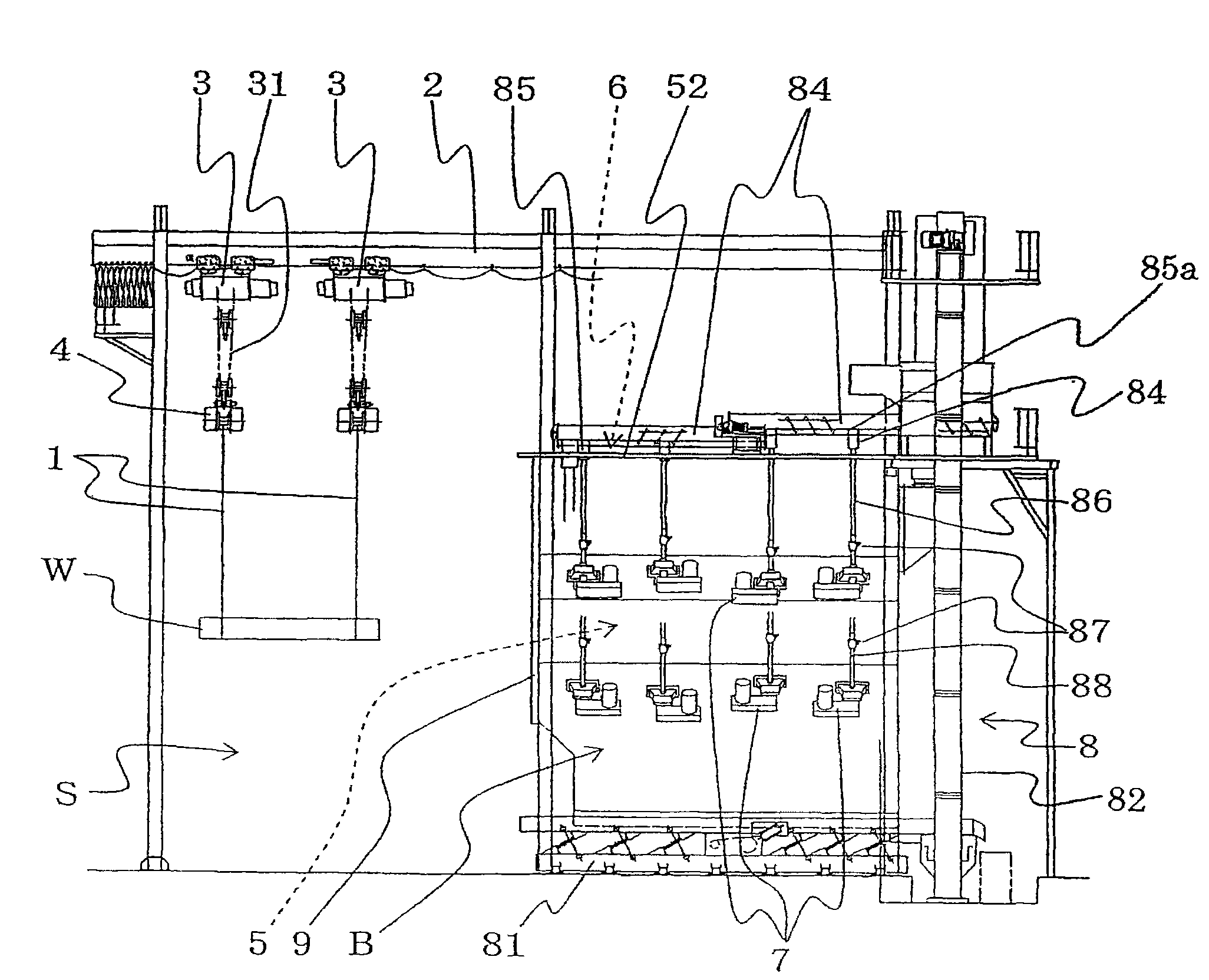
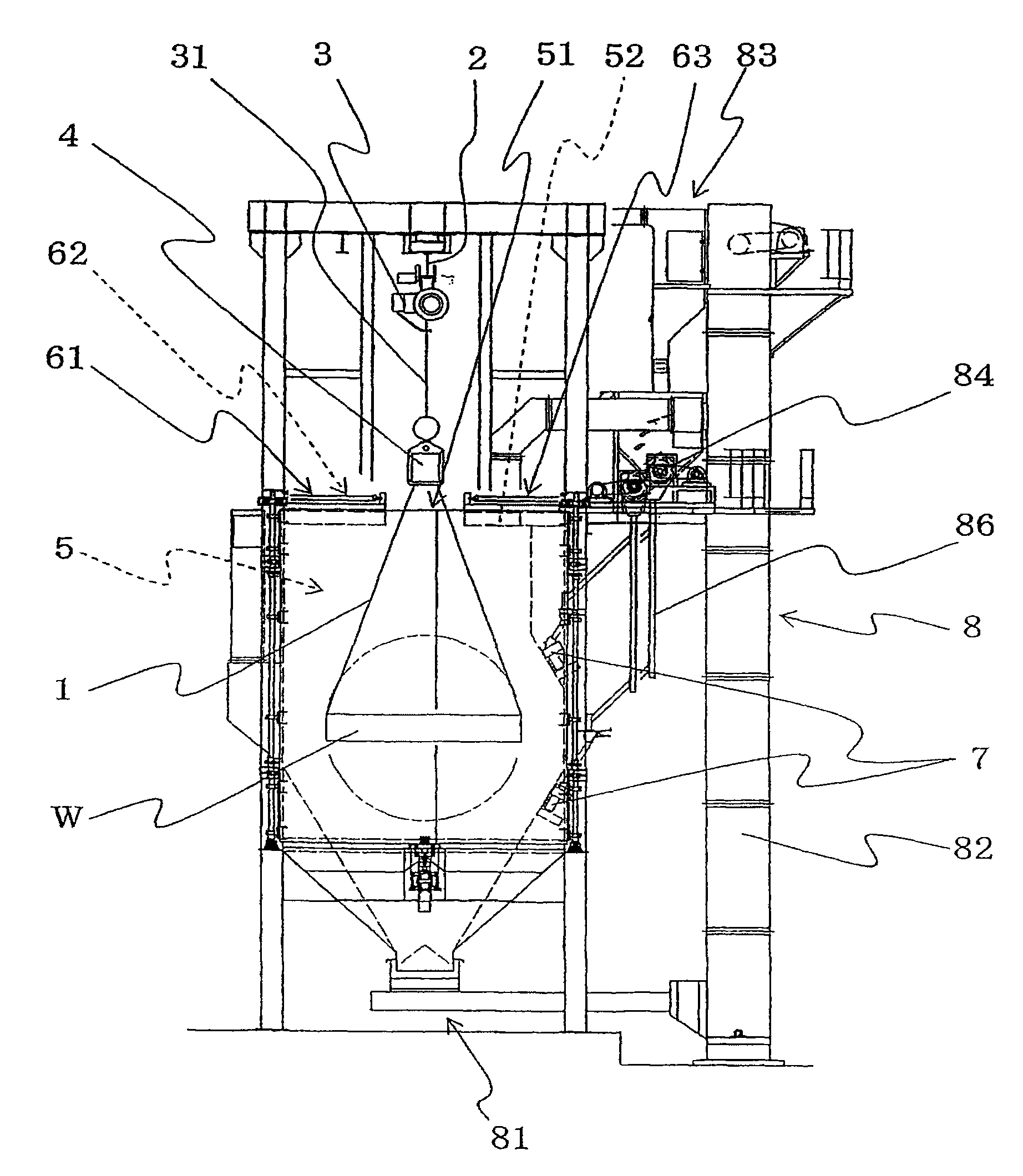
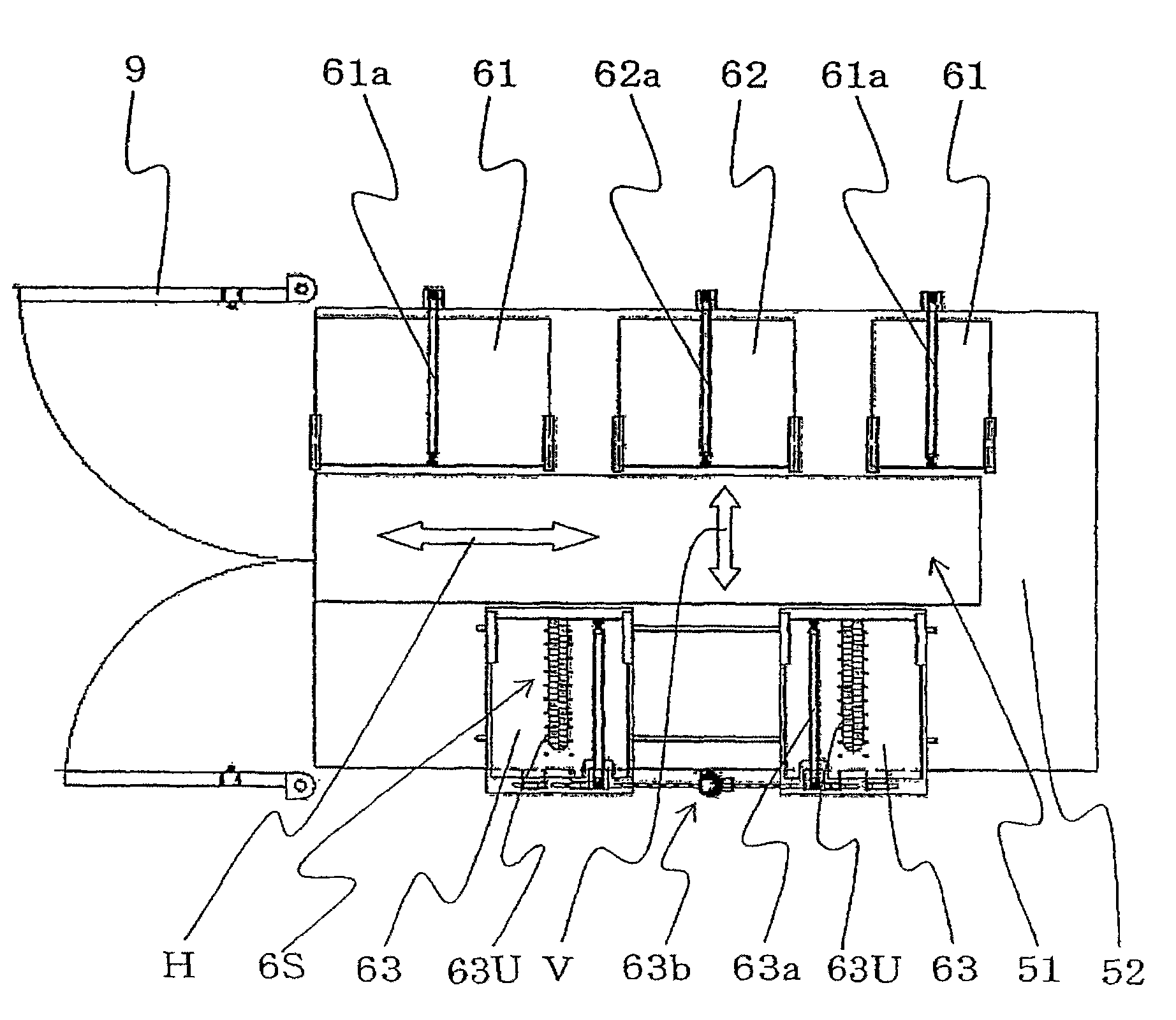
[0018] Such as figure 1 , figure 2 with image 3 A horizontal rail 2 is provided on the upper part of the shot blasting device in the illustrated embodiment, and the rail 2 can bear the load caused by the suspension of the workpiece W. The track 2 extends from above a working area S to above an enclosure B, which is the area where the workpiece W is wound on and released from a chain sling 1, the The enclosure B defines a projection chamber 5.

[0019] The rail 2 is provided with two elevators 3 (vertical moving devices) that can move along the rail 2, and the elevator 3 can also be moved vertically by, for example, a steel wire 31. Suspended on each steel wire 31 of each elevator 3 is a reversing machine 4. The reversing machine 4 includes a chain sling 1 which is an annular member formed by a chain connected end to end, and a sending mechanism for sending out the chain sling 31. The length of the chain sling 1 is such that at least part of the circumference of the workpiece ...


PUM


Abstract

A shot-blasting machine for shot blasting a workpiece is disclosed. The shot-blasting machine comprises a rail 2 mounted on an upper part of the shot-blasting machine and extending in a horizontal direction, one or two hoists movable along the rail, and two inverting mechanisms 4. Each inverting mechanism 4 includes chain slings 1 for supporting one workpiece W at one end or the other end such that the workpiece W is suspended therefrom and includes a feeder for feeding the chain sling 1. An enclosure B in the shot-blasting machine has an entrance at one side and defines a projecting chamber 5therein. The upper surface of the enclosure B is provided with an elongated opening 51. The volume of the projecting chamber 5 is to allow the workpiece W supported by the chain slings 1 to be movedalong the direction that the rail 2 extends by running the hoist 3, while the workpiece W can be rotated about a rotating axis that is parallel to the direction that the rail 2 extends. The upper surface of the enclosure B is provided with a sealing mechanism 6 for preventing the shots from dispersing from the opening 51 by closing the opening 51 in which the chain slings 1 are inserted.

Description

Technical field [0001] The invention relates to a shot peening device, in particular to a shot peening device suitable for processing large metal products. Background technique [0002] Japanese Patent No. 9-047966 owned by the assignee of the present application discloses a conventional shot blasting device for processing large metal products as a workpiece, and the device has a turntable. In this device, the workpiece is placed on a turntable to rotate and polish it. [0003] However, in the shot blasting device with a turntable, when a large metal product is to be polished, because the workpiece is located on the turntable, the turntable will cause a blind spot in the projection toward the workpiece (for example, the bottom surface of the workpiece, or the workpiece). The part that falls into the shadow of the turntable itself). Therefore, it is impossible to completely polish all the surfaces to be processed of the workpiece. In particular, if the workpiece has a complicated...

Claims


Application Information

Patent Timeline
Patent Type & Authority Applications(China)
IPC IPC(8): B24C3/08B24C3/10B24C3/18B24C9/00
CPCB24C3/085B24C3/18B24C3/10B24C9/00B24C3/083B24C3/08
Inventor 海野勤安藤义信
Owner SINTOKOGIO LTD
Why Eureka
Try Eureka