
Pruning shears

一种修枝剪、刀片的技术,应用在修枝剪领域,能够解决方案复杂、不可靠、复杂性使用等问题

Active Publication Date: 2010-03-31
FISKARS FINLAND OY
View PDF2 Cites 6 Cited by
  • Summary
  • Abstract
  • Description
  • Claims
  • Application Information

AI Technical Summary

Problems solved by technology

However, this solution is complex, expensive to manufacture and unreliable to use due to its complexity
It is also difficult for the user to reassemble the patented drive mechanism when it must be opened and disassembled for maintenance or other repair work

Method used


Image

  • Pruning shears
  • Pruning shears
  • Pruning shears

Examples


Embodiment Construction

[0018] The present invention relates to cutting implements, such as pruning shears. However, although the present invention is generally referred to herein as pruning shears, those skilled in the art will appreciate that the mechanisms and principles of operation described herein can be generally applied to a variety of other cutting implements.

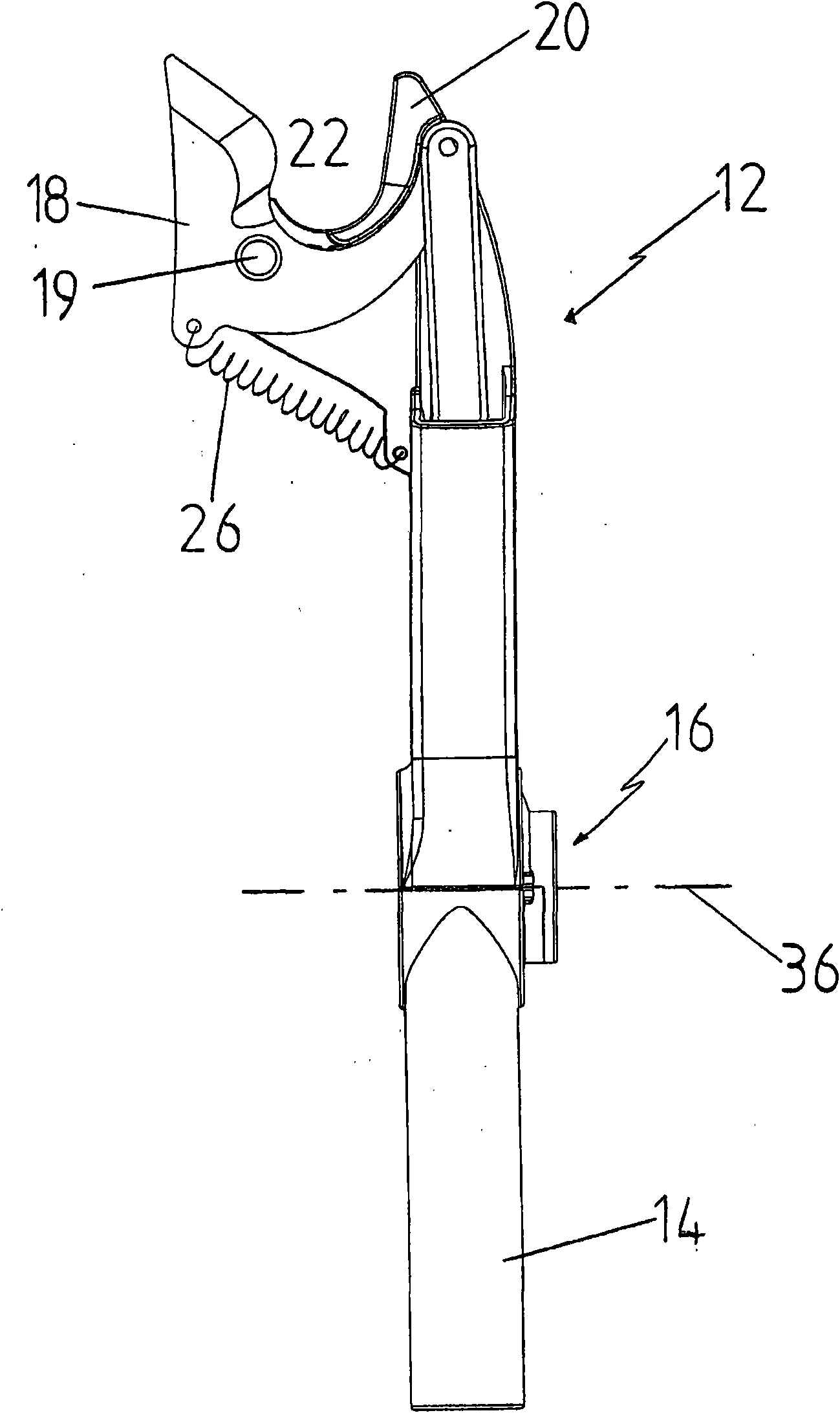
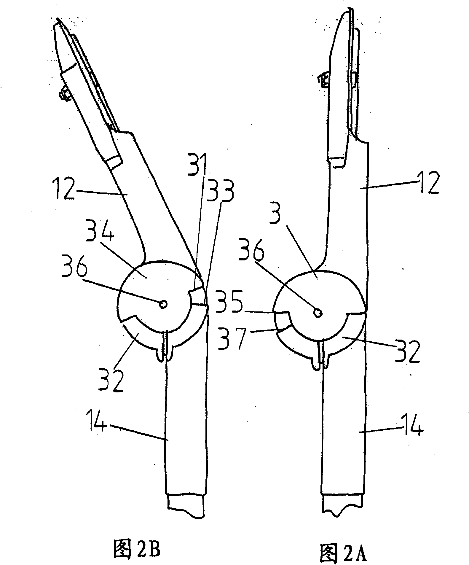
[0019] refer to figure 1 , an embodiment of pruning shears is shown in the figure, which is generally indicated by reference numeral 10 . Pruning shears 10 include a cutting head 12 for pruning, pruning and pruning, an elongated handle (only a portion of which is shown) and a drive mechanism 16 disposed between the cutting head 12 and the handle 14. . The cutting head 12 includes a blade 18 that is rotatable about a hinge point 19 and cooperates with an opposing blade 20 to form a jaw 22 that will receive a workpiece to be cut by the blade 18 . A spring 26 (schematic) tensions the blade 18 into an open position relative to the opp...


PUM


Abstract

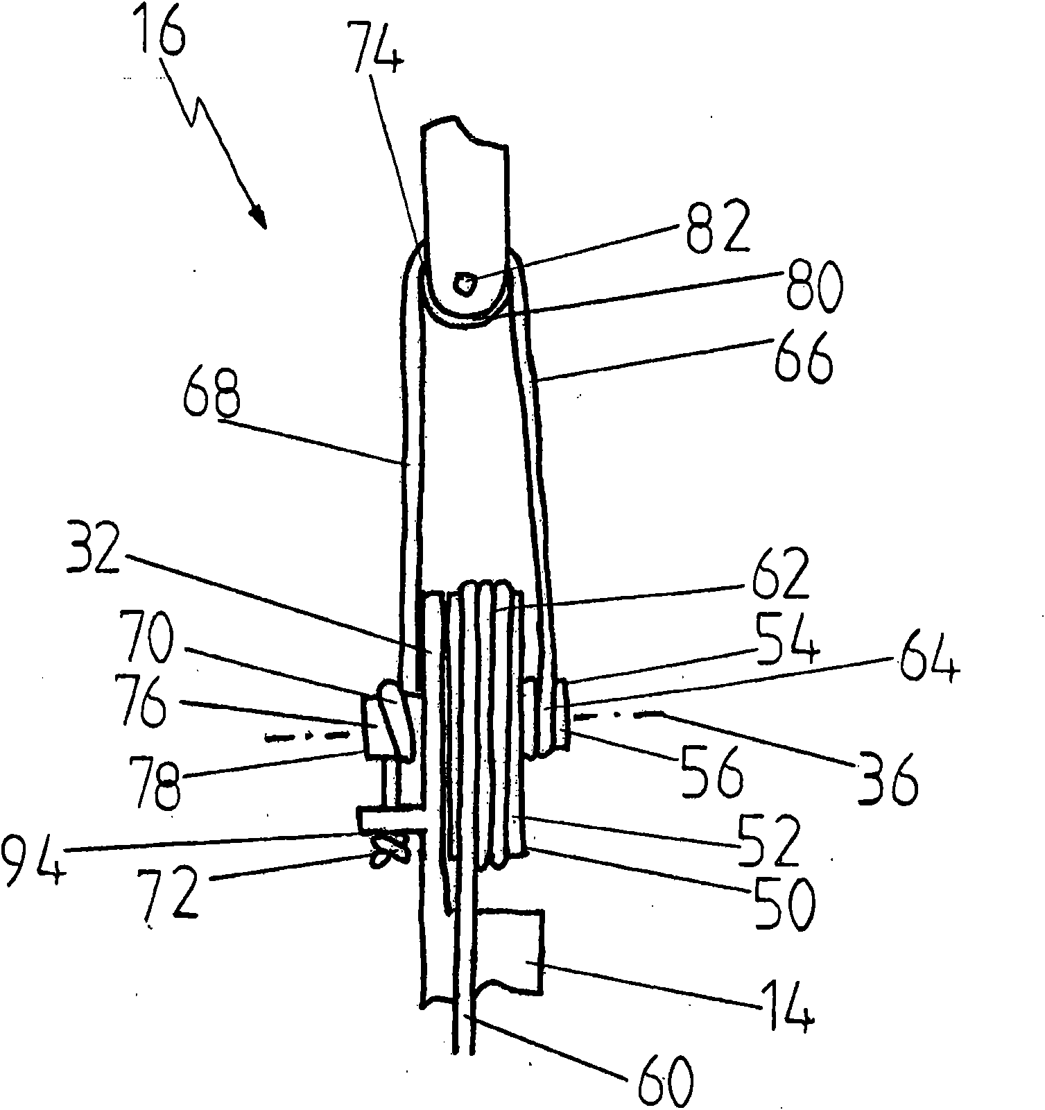
The invention relates to pruning shears comprising a cutting head (12) with a spring-loaded blade (18) acting in cooperation with a counter blade (20), a drive mechanism (16) connected to the cuttinghead (12), and an elongated handle (14) connected to the drive mechanism (16). The drive mechanism comprises a first and a second counterpart (32, 34), optionally rotating with respect to one anotherabout an axis (36), allowing the cutting head (12) to be adjusted with respect to the elongated handle (14), and an upper line arrangement allowing the blade (18) to be turned about a hinge point (19)and the cutting head to be adjusted in such a manner that the blade (18) does not rotate about the hinge point (19).

Description

technical field [0001] The present invention relates generally to shearing tool technology, and in particular to pruning shears according to the preamble of claim 1, comprising a cutting head with a spring-loaded blade with a pivotable hinge point a pivotal opposing blade connection with which the opposing blade cooperates for cutting a workpiece received in a clamp provided by the opposing blade; a drive mechanism which is connected to the cutting head; an elongated handle with which the elongated The handle is connected to a drive mechanism that includes first and second opposing members that are selectively rotatable about an axis relative to each other to enable adjustment of the cutting head relative to the elongated handle, whereby the first opposing member and the elongated handle connection, the second opposing part is connected to the cutting head; a first wheel, which rotates about an axis; and a drive wire, which is arranged to cause the first wheel to rotate when p...

Claims


Application Information

Patent Timeline
Patent Type & Authority Applications(China)
IPC IPC(8): B26B17/02B26B13/26A01G3/025
CPCA01G3/025A01G3/0255B26B13/26B26B17/02
Inventor O·林登M·帕洛黑莫
Owner FISKARS FINLAND OY
Learn More