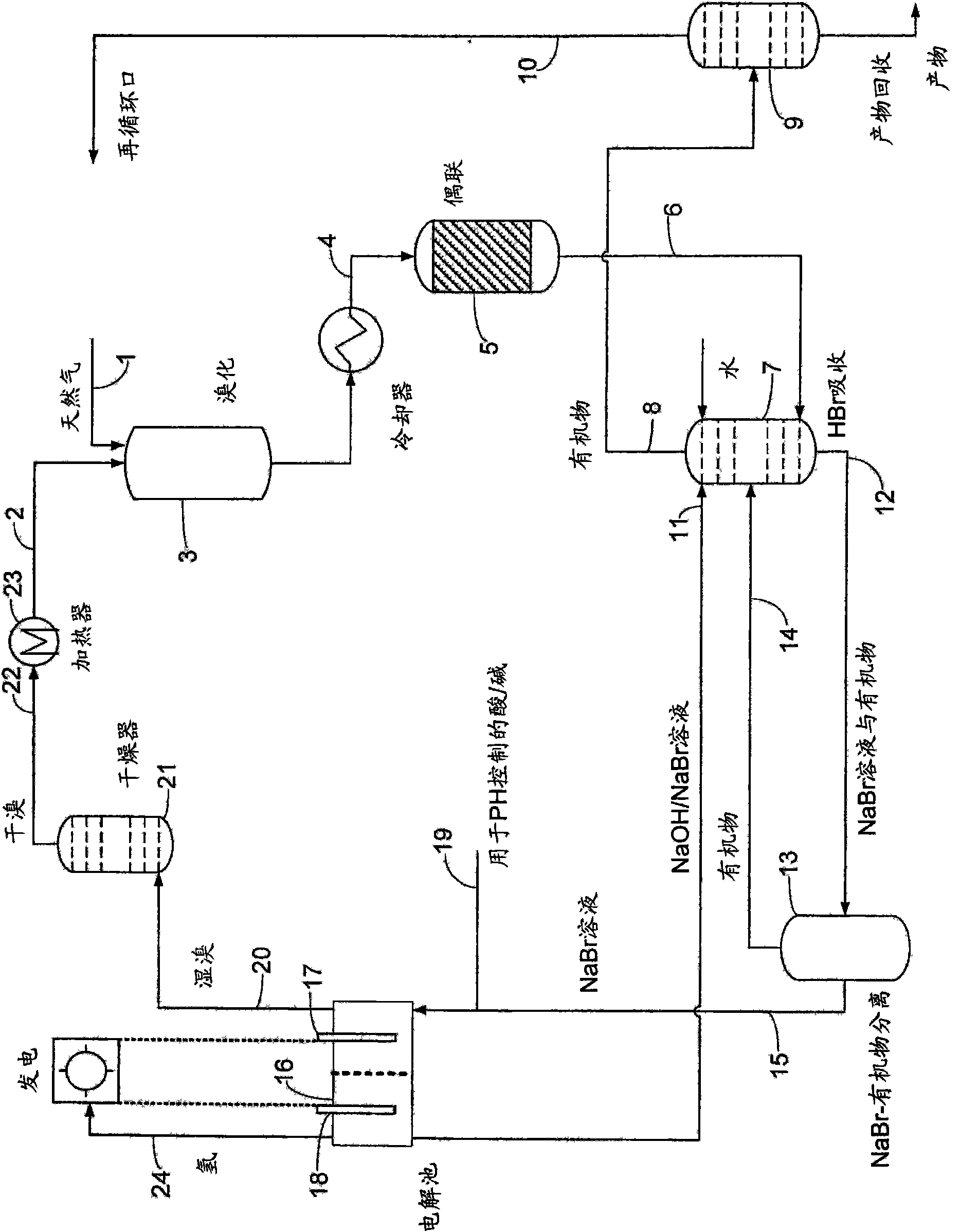
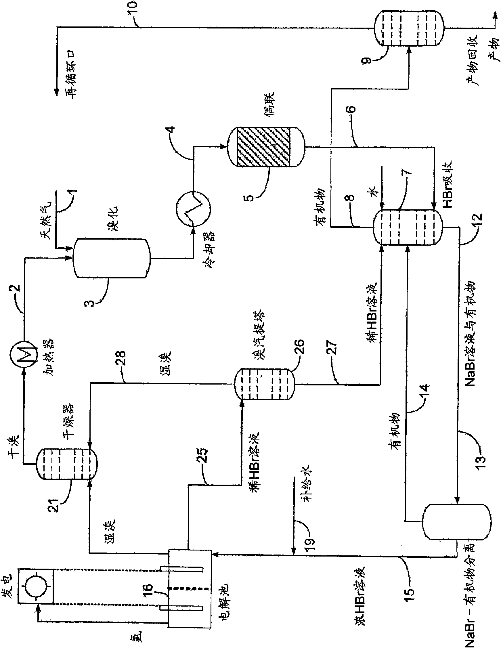
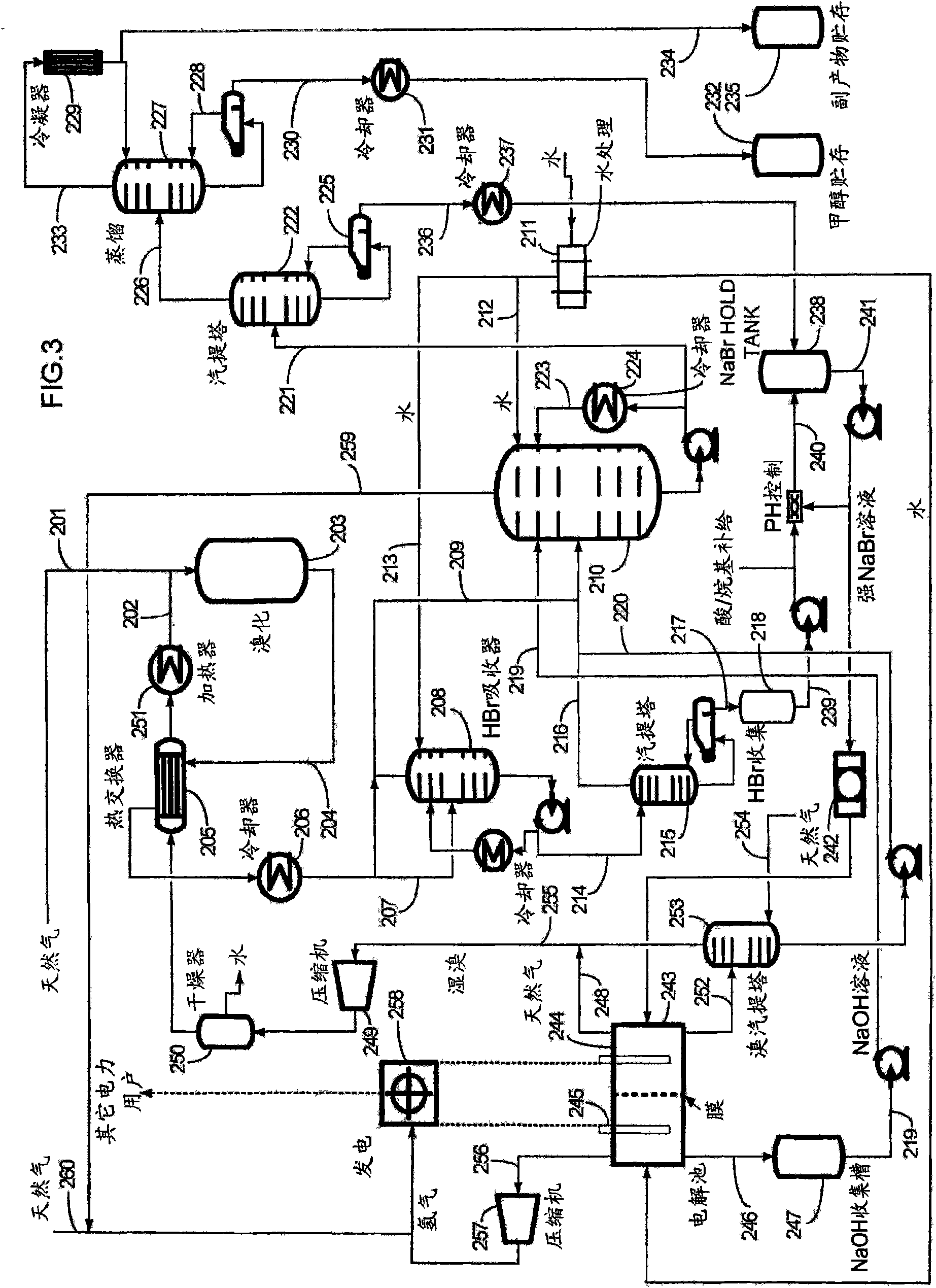
Process for converting hydrocarbon feedstocks with electrolytic recovery of halogen
A technology for hydrocarbon raw materials and halogens, which is applied in the field of converting hydrocarbon raw materials while electrolytically recovering halogens, to achieve the effect of simple by-products
- Summary
- Abstract
- Description
- Claims
- Application Information
AI Technical Summary
Problems solved by technology
Method used
Image
Examples
Embodiment 1
[0101] Example 1 Methane bromination
[0102] Methane (11 sccm, 1.0 atm) was mixed with nitrogen (15 sccm, 1.0 atm) through a tee at room temperature and passed through a bromine-filled bubbler at 18°C. CH 4 / N 2 / Br 2 The mixture is passed to a preheated 500°C glass tube (inner diameter 2.29cm, length 30.48cm, filled with glass beads), where methane bromination reaction occurs with a residence time of 60 seconds, mainly producing methyl bromide, methylene bromide and HBr:
[0103] CH 4 +Br 2 →CH 3 Br+CH 2 Br 2 +HBr
[0104] As the products leave the reactor, they are collected by a series of traps containing 4M NaOH for neutralization of HBr and containing hexadecane to dissolve as much hydrocarbon product as possible (with octadecane as internal standard). Volatile components (such as methane) are collected in the gas bag after the HBr / hydrocarbon trap.
[0105] After the bromination reaction, the coke or carbonaceous deposits were burned in a hot air stream (5 scc...
Embodiment 2
[0106] Example 2 CH 3 Coupling of Br to light olefins
[0107] 2.27 g of 5% Mg doped ZSM-5 (CBV8014) zeolite was placed in a tubular quartz reactor (1.0 cm ID) which was preheated to 400°C prior to the reaction. will pass N 2 Diluted CH 3 Br is pumped to the reactor, CH is controlled by a micro liquid pump 3 Br flow rate 24μl / min, N 2 The flow rate is 93.3ml / min. CH 3 The Br coupling reaction was carried out on the catalyst bed with a residence time of 0.5 sec, CH 3 The partial pressure of Br was 0.1, which was set according to the flow rate.
[0108] After 1 hour of reaction, the product exited the reactor and was collected by an in-line trap containing 4M NaOH to neutralize the HBr and containing hexadecane to dissolve as much hydrocarbon product as possible (with octadecane as an internal standard ). Volatile components such as methane and light olefins are collected in the air bag after the HBr / hydrocarbon trap.
[0109] After the coupling reaction, the coke or c...
Embodiment 3
[0111] Example 3 CH 3 Br coupled to BTX
[0112] Mn ion-exchanged ZSM-5 zeolite (CBV3024, 6 cm in length) pellets were loaded into a tubular quartz reactor (ID, 1.0 cm), which was preheated to 425° C. before the reaction. N 2 Diluted CH 3 Br is pumped to the reactor, CH is controlled by a micro-pump 3 Br flow rate 18μl / min, N 2 Flow rate 7.8ml / min. CH 3 The Br coupling reaction was carried out on the catalyst bed with a residence time of 5.0 sec, CH 3 The Br partial pressure is 0.5, set according to the flow rate.
[0113] After 1 hour of reaction, the product exited the reactor and was collected through an in-line trap containing 4M NaOH for neutralization of HBr and containing hexadecane to dissolve as much hydrocarbon product as possible (octadecane was included as an internal standard). Volatile components such as methane and light olefins are collected in the air bag after the HBr / hydrocarbon trap.
[0114] After the coupling reaction, the coke or carbonaceous de...
PUM
 Abstract
Description
Claims
Application Information
 - R&D
- Intellectual Property
- Life Sciences
- Materials
- Tech Scout
- Unparalleled Data Quality
- Higher Quality Content
- 60% Fewer Hallucinations
Browse by: Latest US Patents, China's latest patents, Technical Efficacy Thesaurus, Application Domain, Technology Topic, Popular Technical Reports.
© 2025 PatSnap. All rights reserved.Legal|Privacy policy|Modern Slavery Act Transparency Statement|Sitemap|About US| Contact US: help@patsnap.com


