

Gas spring assembly
一种气弹簧、组件的技术,应用在弹簧、车辆弹簧、弹簧/减震器等方向,能够解决不能衰减振动频率范围等问题
- Summary
- Abstract
- Description
- Claims
- Application Information
AI Technical Summary
Problems solved by technology
Method used
Image

Examples
Embodiment Construction
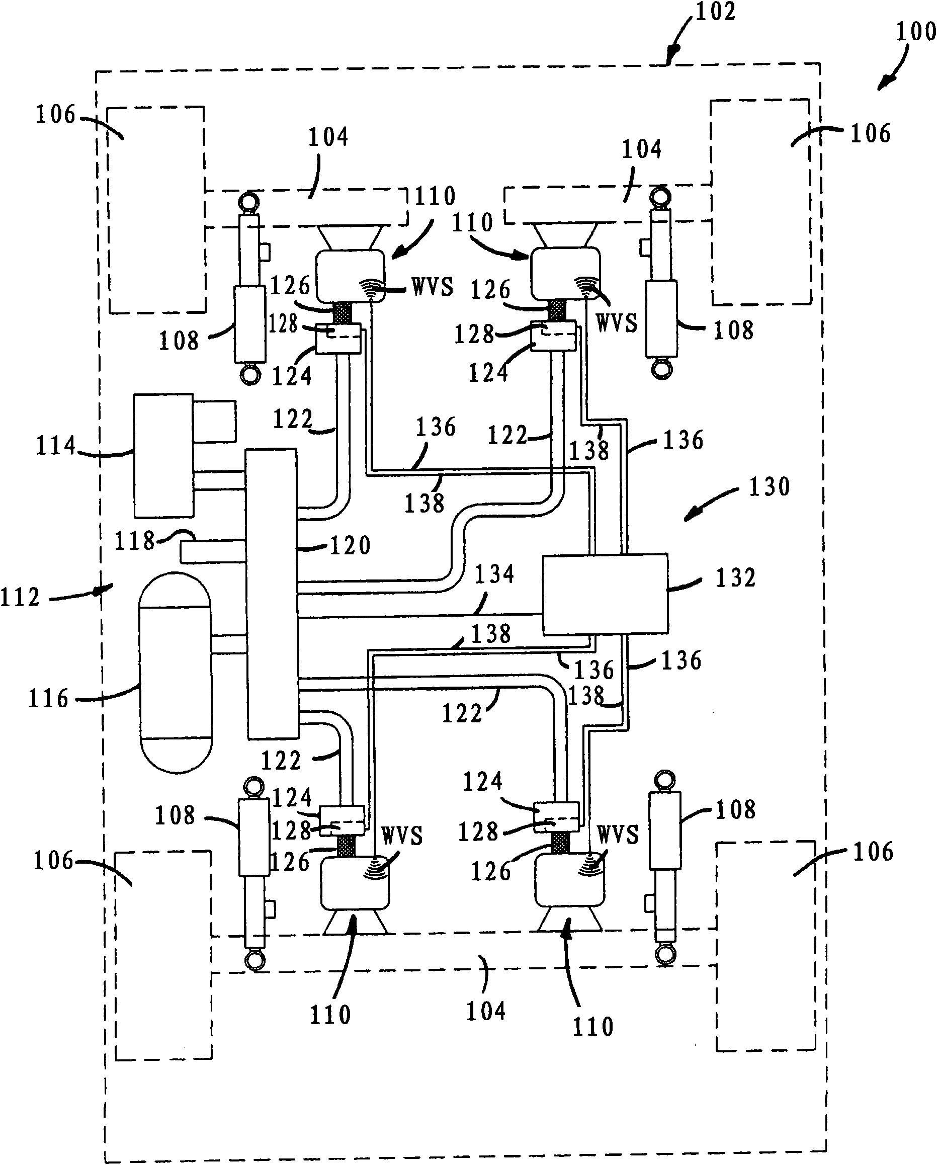
[0045] Turning now to the drawings, which are shown in order to illustrate exemplary embodiments of the novel concept and not to limit it, figure 1 A vehicle 100 is shown having a sprung mass, such as for example a body 102 , and an unsprung mass, such as for example an axle 104 and / or wheels 106 . In addition, a plurality of hydraulic dampers, such as the shock absorber 108, can be fixed in a suitable manner between the sprung and unsprung masses of the vehicle. However, it will be appreciated that such dampers may optionally be included in figure 1 in a typical embodiment. Additionally, a plurality of gas spring assemblies 110 (which may also be referred to herein as "gas spring and gas damper assemblies") are disposed between the sprung and unsprung masses of the vehicle, such as figure 1 Between the adjacent wheel 106 and the shock absorber 108 shown in .
[0046] The vehicle 100 also includes a pressurized gas system 112 in communication with the gas spring assembly 11...
PUM
 Abstract
Description
Claims
Application Information