Annular porous flow disturbing structure of gas flow adjusting device of solid rocket engine

A gas flow adjustment and flow adjustment device technology, which is applied to rocket engine devices, jet propulsion devices, machines/engines, etc., can solve the problem of uneven force on the spool of the flow adjustment device, structural damage of the flow adjustment device, and rocket engine thrust. Eccentricity and other problems can be achieved to reduce local erosion and ablation, simple structure, and reduce aerodynamic shock and side load

Inactive Publication Date: 2016-07-06
SHANGHAI XINLI POWER EQUIP RES INST
View PDF6 Cites 9 Cited by
  • Summary
  • Abstract
  • Description
  • Claims
  • Application Information

AI Technical Summary

Problems solved by technology

The gas temperature of the solid attitude orbit control rocket engine is as high as 2000K, and the gas flow rate is high. The gas flow adjustment device is located at one end of the engine. The incoming flow of gas will cause uneven force on the spool of the flow regulating device, and also cause problems such as thrust eccentricity of the solid attitude and orbit control rocket engine; in more serious cases, the structure of the flow regulating device will be damaged, the engine nozzle will burn through and the engine will explode catastrophic accident

Method used


Image

  • Annular porous flow disturbing structure of gas flow adjusting device of solid rocket engine
  • Annular porous flow disturbing structure of gas flow adjusting device of solid rocket engine
  • Annular porous flow disturbing structure of gas flow adjusting device of solid rocket engine

Examples


Embodiment Construction

[0012] The invention will be described in more detail hereinafter with reference to the accompanying drawings showing embodiments of the invention. However, this invention may be embodied in many different forms and should not be construed as limited to the embodiments set forth herein.

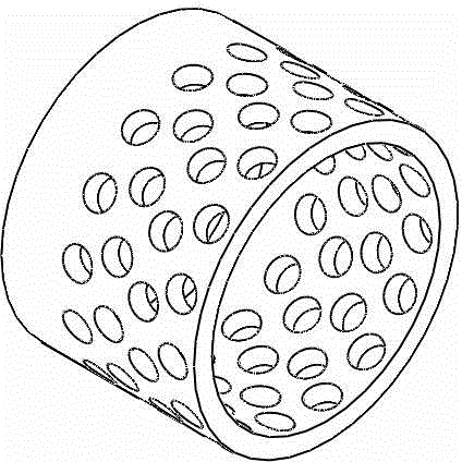
[0013] Such as figure 1 As shown, the annular porous spoiler structure of the solid rocket motor gas flow regulating device of the present invention is characterized by an annular porous structure. The spoiler structure can be made of high-temperature resistant alloy materials, composite materials or high-temperature structural ceramic materials. There are multiple (number ≥ 3) circular or other required shape ventilation holes. Multiple ventilation holes can be placed in the same circle or multiple circles. The ventilation holes can be arranged evenly in the circumferential direction, or they can be arranged in different positions according to the use requirements. place layout.

[0014] S...


PUM


Abstract

The invention proposes an annular porous gas turbulence structure of a solid rocket motor gas flow regulating device, which premixes and evenly distributes the high-temperature and high-speed incoming gas, reduces the uneven erosion and aerodynamic impact of the gas on the valve core of the flow regulating device, and can also be used To filter some of the bulky debris entrained in solid rocket motor gases. The annular porous gas turbulence structure can process multiple air holes on the annular turbulence structure according to the incoming flow direction. The shape and number of air holes can be adjusted according to the area of ​​the gas inlet and nozzle outlet. The periphery of the spool of the regulating device is fixed between the gas inlet and the spool of the flow regulating device through mechanical and adhesive means. The invention not only has the characteristics of simple structure, compactness, easy molding, convenient assembly, high temperature resistance, reliable operation, etc.; it also plays the role of premixed gas flow, uniform distribution of gas, and reduces local erosion and ablation of high-temperature and high-speed gas on the gas flow adjustment device. .

Description

technical field [0001] The invention relates to the technical field of jet propulsion devices, in particular to a gas flow turbulence structure suitable for regulating the gas flow of a solid attitude and orbit control rocket engine and splitting the flow evenly. Background technique [0002] The solid attitude and orbit control rocket engine is a control method that uses the direct reaction effect of the rocket engine gas to generate lateral maneuvering control torque and force. The former uses the engine installed at a certain distance from the center of mass of the missile to generate control torque to quickly establish the angle of attack, and the lateral overload is generated by aerodynamic force. Its typical application is the PAC-3 ("Patriot-3") missile of the United States; the latter will The engine is arranged at the center of mass of the missile to directly generate lateral overload. Its typical applications are the two small missiles 9M96E and 9M96E2 of the Russi...

Claims


Application Information

Patent Timeline
Patent Type & Authority Applications(China)
IPC IPC(8): F02K9/32
Inventor 杨永强牛禄刘晓丽李海涛周伟华王勇张汉秀张训国邹贤
Owner SHANGHAI XINLI POWER EQUIP RES INST
Why Eureka
Try Eureka