

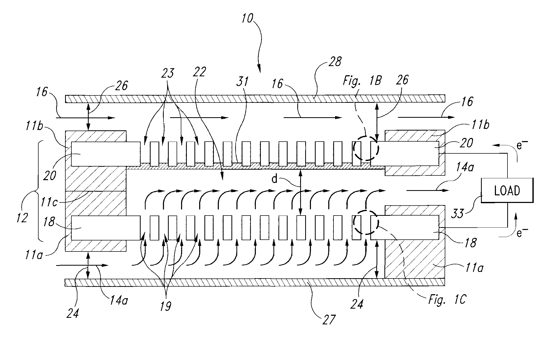
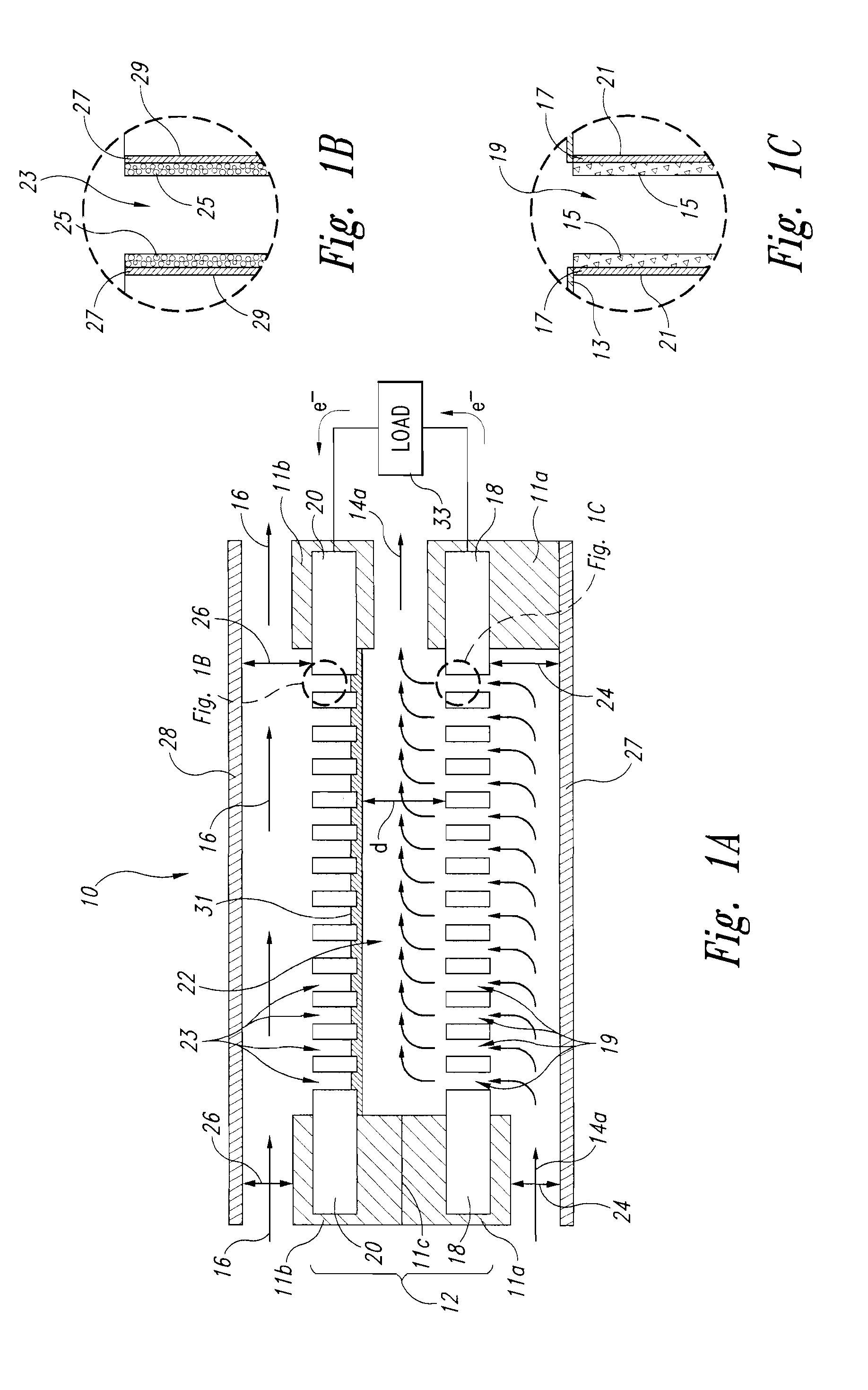
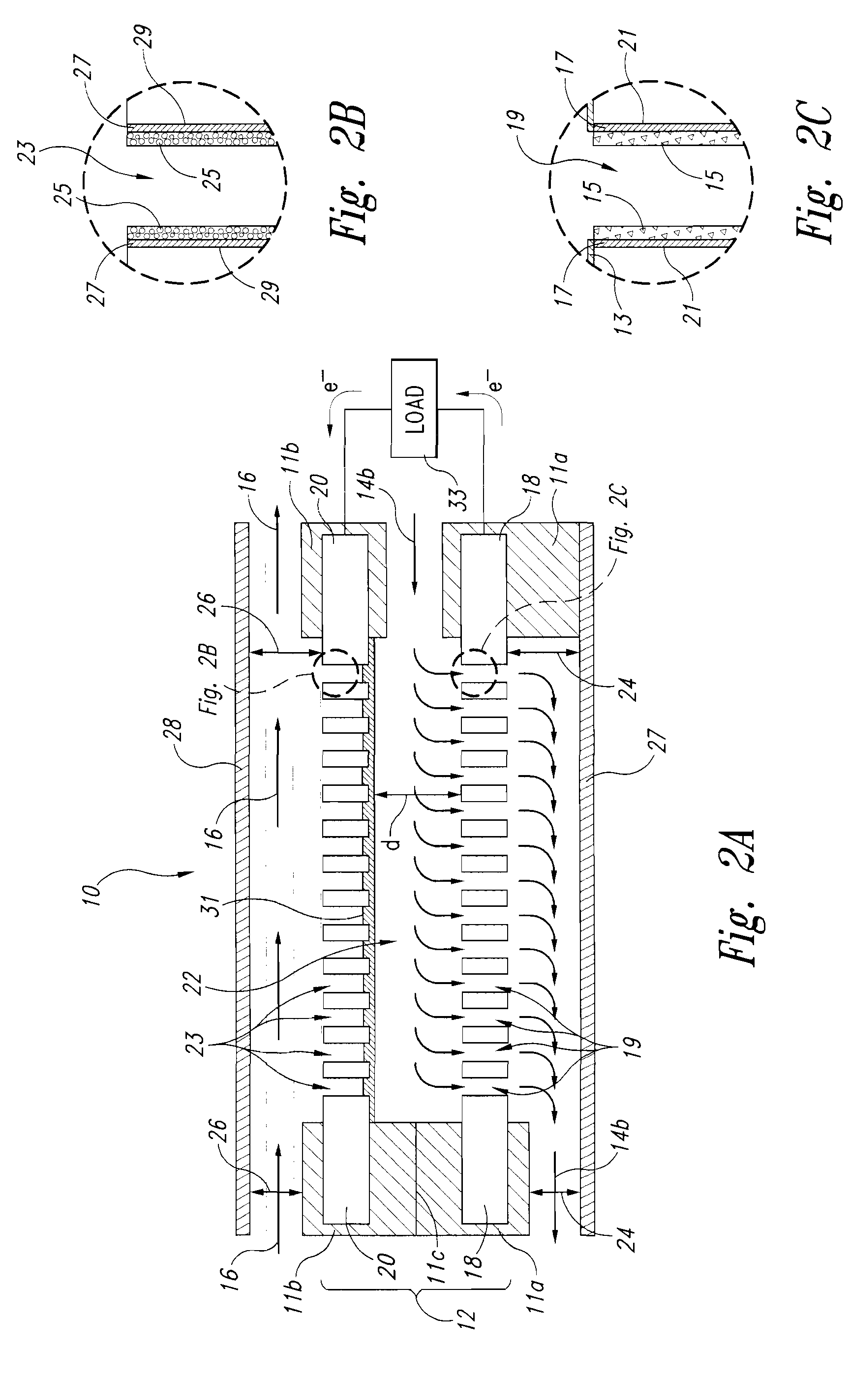
Liquid-liquid fuel cell systems having flow-through anodes and flow-by cathodes
a fuel cell and liquid-liquid technology, applied in the field of microfluidic fuel cell systems, can solve the problems of large technical limitations of known fuel cell systems, inability to meet the needs of micro-scale pem-based methanol-air fuel cell systems, and inability to meet the needs of micro-scale pem-based methanol-air systems,
- Summary
- Abstract
- Description
- Claims
- Application Information
AI Technical Summary
Benefits of technology
Problems solved by technology
Method used
Image

Examples
example 1
Manufacturing Steps Used to Make Silicon-Based Anode Structures
[0039]Step 1. Wafer Spec: Si Wafers were provided by Wacker-Siltronic (Munich, Germany) wherein each wafer had an approximate 3000-3500 Å layer of Low Temperature Oxide (LTO) on the front side and with approximate specifications as set forth in the Table below.
TABLE 1SILICON WAFER SPECIFICATIONSCrystalDopantρDifPrimaryDiameterThicknessOrientTypeType[Ω-TTVGrowthLengthGradeFat[mm][μm][—][—][—]cm][μm][—][μm][—][μm]100550100Pn20-30CZ>400Hi-Ref30-35[0040]Step 2. Wafer Cleaning: A single wafer was cleaned with Nanostrip, then in BOE, and then with a spin rinse dryer (SRD).[0041]Step 3. Al Contact Doping: The wafer was doped by using a spin on dopant on the backside and inserting into a furnace.[0042]Step 4. Photolithography: The front side of the wafer was then patterned with photoresist (namely, and ordered array of 5 μm squares with an 8 μm pitch).[0043]Step 5. RIE: The patterned LTO was etched using an RIE (reactive ion etc...
example 2
Manufacturing Steps Used to Make Silicon-Based Cathode Structures
[0068]Steps 1-24 are the same as steps 1-24 set forth above in Example 1.[0069]Step 25. Catalyst Deposition: A catalyst ink was prepared by homogenizing about 250 mg of Pt:Ru black and about 1,250 mg of 5% Nafion solution in a mixture of solvents in a sonicator. Then appropriate amounts of the ink were applied to the surface of the die to yield a catalyst loading of about 30 mg / cm2.[0070]Step 26. Sinter: The coated die was then sintered.
example 3
Manufacturing Steps Used to Make Alternative Cathode Structures
[0071]Steps 1-19 are the same as steps 1-19 set forth above in Example 1.[0072]Step 20. Metallization: An approximate 5000 Å gold film was deposited on the both sides of the wafer using PVD.[0073]Step 21. Metal Anneal: The gold was annealed by placing in a preheated furnace.[0074]Step 22. Dice: The wafer was diced into two 3 cm×8 cm dies.[0075]Step 23. Wafer Cleaning: The dies were cleaned in DI Water and EtOH.[0076]Step 24. Catalyst deposition: A solution of about 250 mg Pt black, 50 mg PTFE (Teflon), and 25 mL Acetone was homogenized for 0.5-1 min in a sonicator. Each silicon die was wetted with Acetone. Then about 2 mL of the solution was evenly distribute over the surface of the coupon. Then the surface of the die was washed with DI H2O. The desired content was about 5:1 of Pt black to PTFE.[0077]Step 25. PVDF Film: A PVDF (poly vinylidene fluoride) membrane (hydrophilic membrane) was placed on top of the catalyst la...
PUM
| Property | Measurement | Unit |
|---|---|---|
| flow rate | aaaaa | aaaaa |
| distance | aaaaa | aaaaa |
| thickness | aaaaa | aaaaa |
Abstract
Description
Claims
Application Information