Dispenser assembly having a porous flow control member

a technology of flow control and dispensing device, which is applied in the direction of liquid dispensing, liquid transferring device, packaging, etc., can solve the problems of difficult control of seltzer bottles, affecting and affecting the convenience of bulk purchasing, so as to reduce waste and improve the economics of bulk purchasing

Active Publication Date: 2005-11-03
PEPSICO INC
View PDF14 Cites 9 Cited by
  • Summary
  • Abstract
  • Description
  • Claims
  • Application Information

AI Technical Summary

Benefits of technology

[0009] Accordingly, the present invention advantageously provides an easy-to-use dispenser assembly that realizes the benefits of both fountain- and seltzer bottle-

Problems solved by technology

Although this arrangement is appropriate for large-scale users such as convenience stores and restaurants, it is less advantageous for smaller-scale users, such as home users.
However, there are several drawbacks associated with this type of seltzer dispenser.
For instance, such seltzer bottles are difficult to control and often are discharged with substantial force, causing the seltzer water to spray out of control.
When seltzer water is dispensed in this manner foaming may occur, which causes the dispensed seltzer water to lose some of its carbonation and become “flat”.
Another drawback with this type of seltzer bottle is that the pressure in the seltzer bottle is often depleted before all the contents of

Method used


Image

  • Dispenser assembly having a porous flow control member
  • Dispenser assembly having a porous flow control member
  • Dispenser assembly having a porous flow control member

Examples


first embodiment

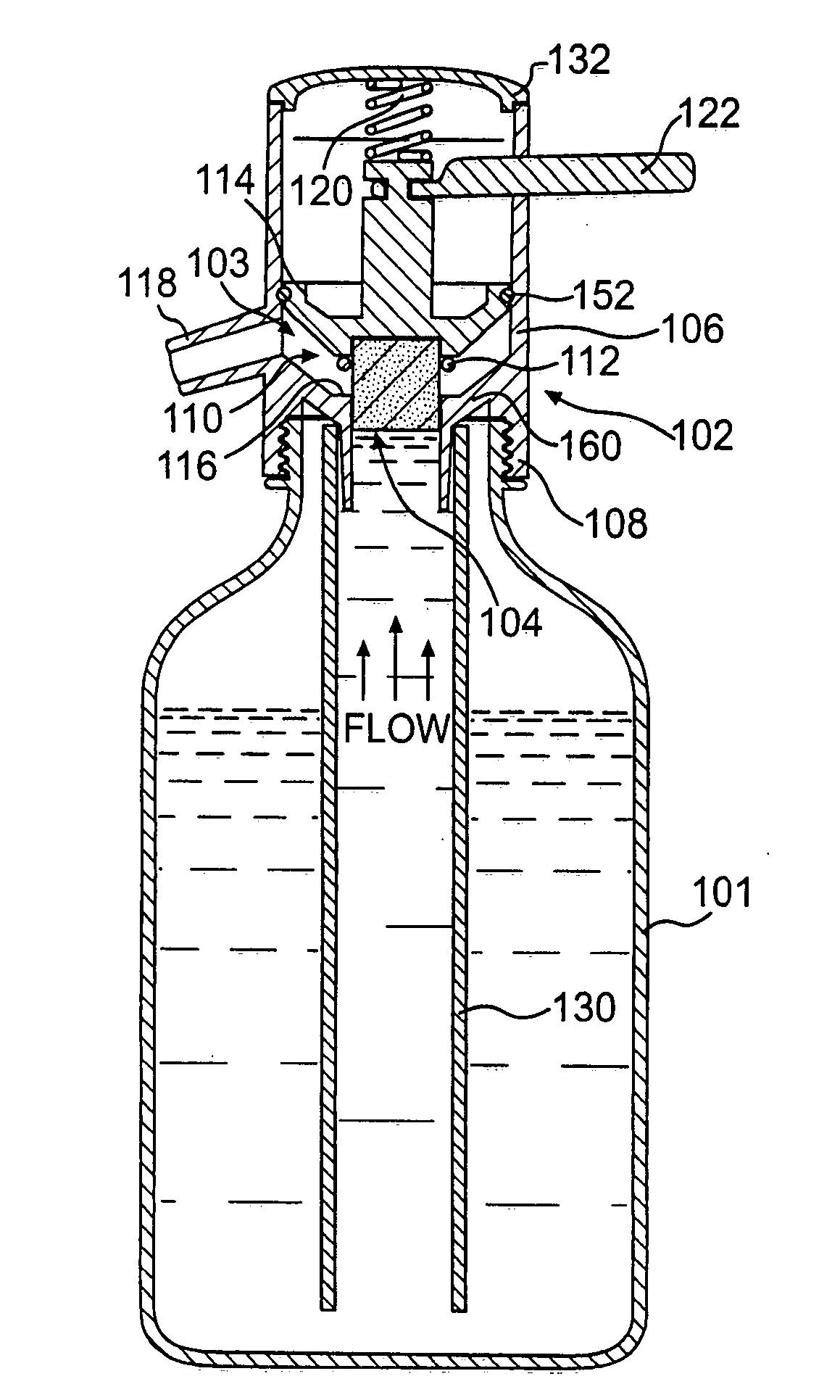
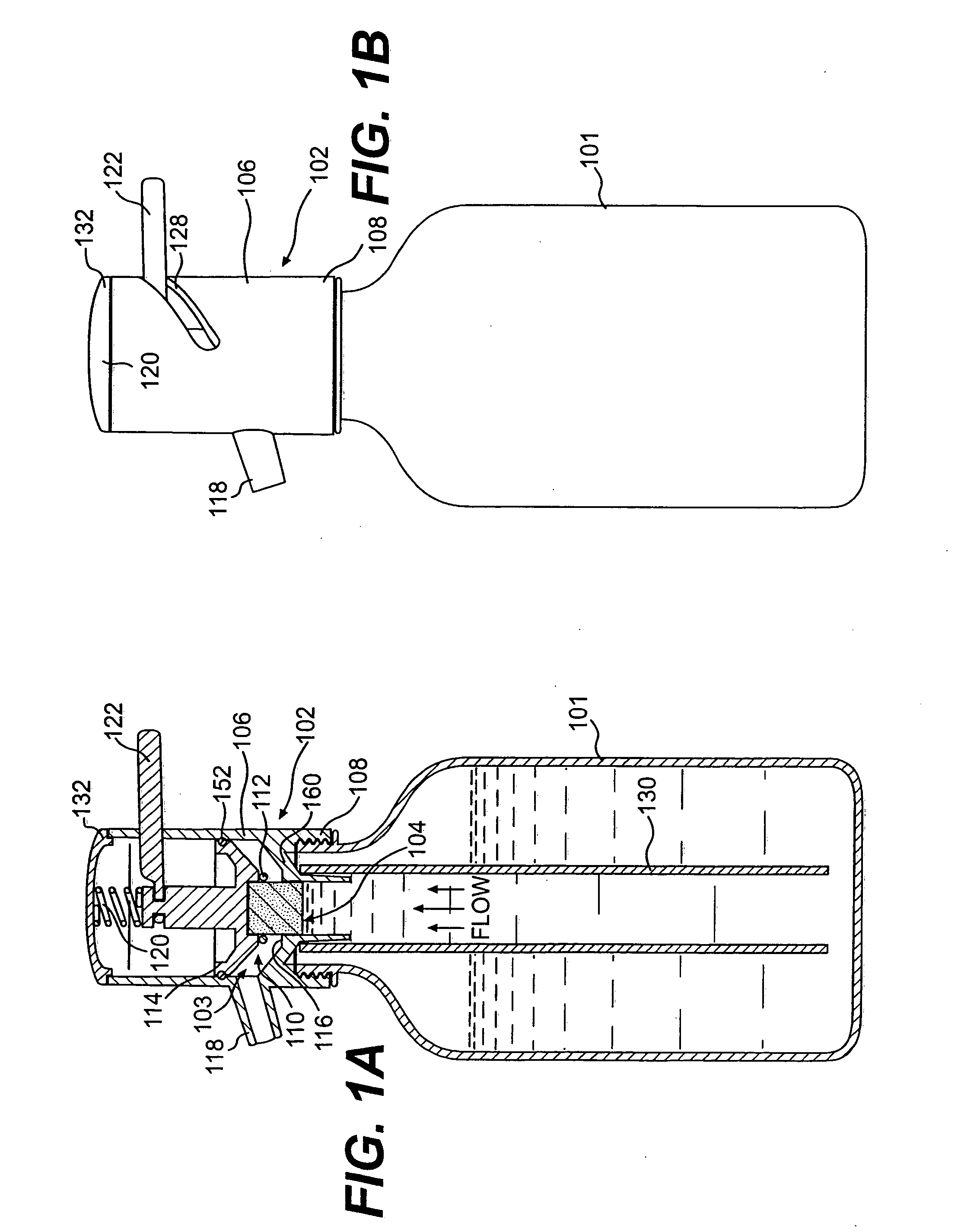
[0047] In a first embodiment of the present invention, illustrated in FIGS. 1A and 1B, the dispenser assembly 102 generally comprises a substantially cylindrical housing 106 for attachment to a container 101, a dispenser body 160 defining a flow passage 103, a PFCM 104 disposed in the flow passage 103, a dip tube 130, a valve 110, and an actuator 122. The dispenser assembly 102 of the first embodiment is operated by a simple manual turn of the actuator 122, whereby a user can easily control the rate of dispensing the beverage by a single motion.

[0048] In this embodiment, the dispenser body 160 is formed integrally with the housing 106 of the dispenser assembly 102. A cap 132 is provided to enclose the working parts in the housing 106. The flow passage 103 is defined in the dispenser body 160 for flow of the beverage out of the container 101 during dispensing. A discharge spout 118 for directing the beverage once it has passed through the flow passage 103 is provided in the side of ...

second embodiment

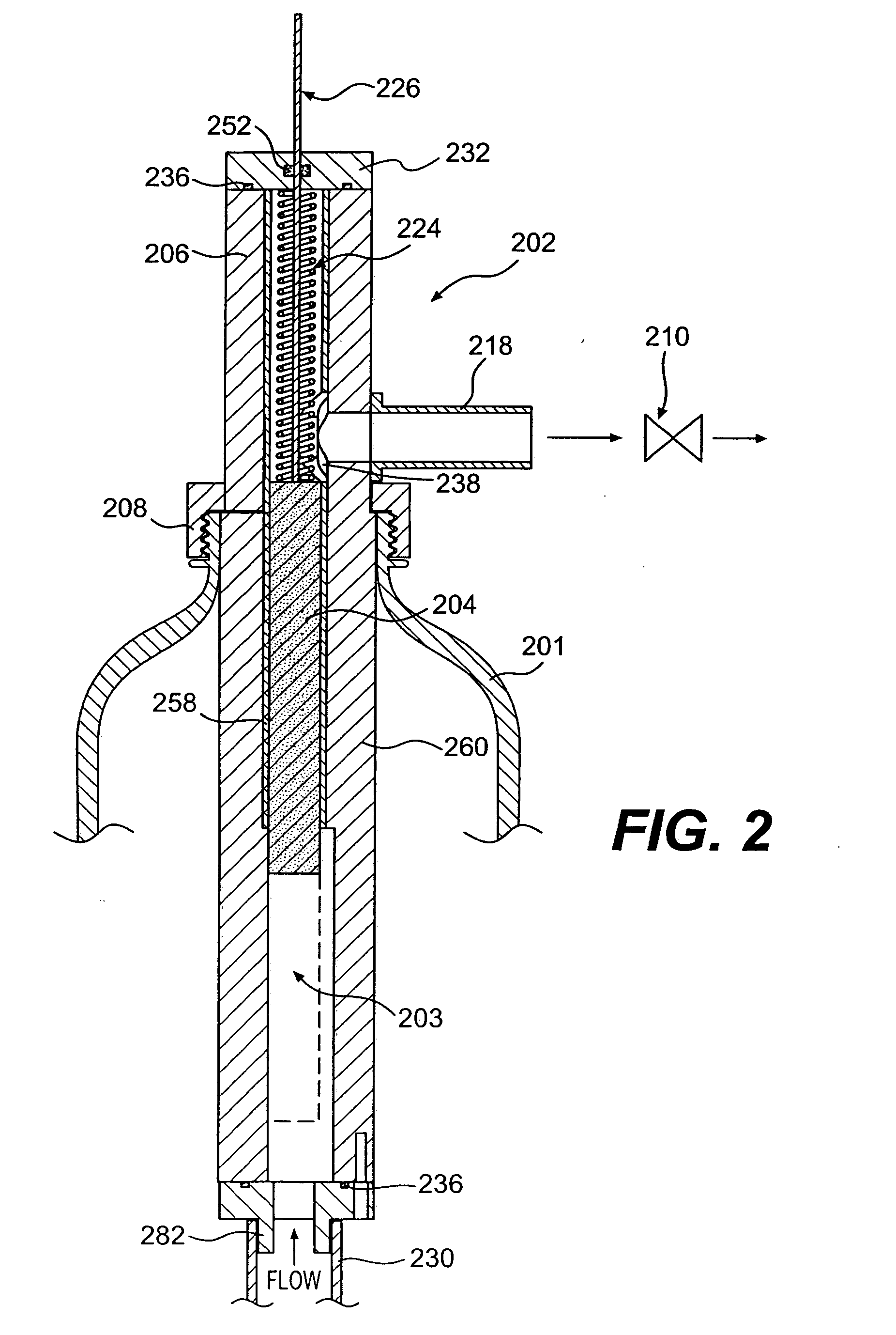
[0053] The dispenser assembly 202 of the second embodiment of the invention functions on similar principles as the first embodiment, in that it uses the pressure contained in a beverage itself to propel the beverage from the container 201, and employs a PFCM 204 to vary the resistance to flow of a beverage during dispensing. However, in the second embodiment, the amount of resistance to flow of the beverage is adjusted automatically, rather than manually as in the first embodiment. That is, the user manually turns the dispenser assembly on and off, but does not have to control the rate at which the beverage is dispensed, this rate being adjusted automatically. As shown in FIG. 2, the dispenser assembly 202 generally comprises a substantially cylindrical housing 206, a dispenser body 260 defining a flow passage 203, a PFCM 204 disposed in the flow passage 203, a dip tube 230, and a valve 210.

[0054] As in the first embodiment, the dispenser body 260 is formed integrally with the subs...

third embodiment

[0059] The third embodiment, shown in FIG. 3, is a manually actuated dispenser assembly 302, similar in operation to the first embodiment in many respects. However, the third embodiment differs from the first embodiment at least in the arrangement of the dispenser body 360, actuator 322, valve 310, and attachment portion 308.

[0060] The dispenser assembly 302 of the third embodiment generally comprises a housing 306, a dispenser body 360 defining a flow passage 303, a PFCM 304 disposed in the flow passage 303, a dip tube 330, a valve 310, and an actuator 322. The dispenser assembly 302 of the third embodiment is operated by twisting the actuator 322, whereby a user can easily control the rate of dispensing the beverage by a single actuator.

[0061] In this embodiment, the dispenser body 360 can be formed separately from the dome-shaped housing 306. A flow passage 303 is defined in the dispenser body 360 for flow of the beverage out of the container 301 during dispensing. A discharge ...


PUM


Abstract

A dispenser assembly that can be used as a dispenser on a container includes a dispenser body having a flow passage, and a porous flow control member positioned in the flow passage such that the liquid must pass through at least a portion of the porous flow control member before being dispensed. The porous flow control member is operable to vary a resistance to flow of the liquid through the dispenser assembly during dispensing. A valve is provided and is movable between an open position that allows the liquid to be dispensed and a closed position that prevents the liquid from being dispensed. A discharge spout directs the flow of liquid discharged from the container. A dip tube is attached to the dispenser body and extends inside the container to supply the liquid to be discharged to the dispenser body. An attachment portion is provided to attach the dispenser assembly to the container.

Description

RELATED APPLICATION [0001] This application claims the benefit of U.S. Provisional Application No. 60 / 553,550 filed Mar. 17, 2004, which application is incorporated ion its entirety into the present application by reference.BACKGROUND OF THE INVENTION [0002] Post-mix fountains for dispensing carbonated beverages, such as sodas, have been used for years in various venues, such as convenience stores and restaurants. Post-mix fountains combine the ingredients of the carbonated beverage (e.g., syrup or concentrate and carbonated water) immediately prior to the beverage begin dispensed into a glass. Such fountains are convenient and economical because they allow the convenience store or restaurant owner to purchase large quantities of syrup or concentrate and carbon dioxide used to make the beverage at bulk prices. Furthermore, less waste is produced and less space is used up by packaging, since the ingredients of the fountain beverage come in large containers, rather than smaller contai...

Claims


Application Information

Patent Timeline
IPC IPC(8): B67D7/76B65D83/00B67D1/00B67D1/04
CPCB67D2210/0001B67D1/0456
Inventor FINLAY, PATRICK J.RITSHER, KENNETH A.COLLINS, JAMES M.SKOSKIEWICZ, ANDRZEJ
Owner PEPSICO INC
Why Eureka
Try Eureka