Optical measuring instrument

A technology of optical measurement and optical measurement equipment, which is applied in the field of optical measurement instruments and optical measurement equipment, and can solve problems such as component failure

Inactive Publication Date: 2010-03-31
凯杰康士坦茨湖有限责任公司
View PDF3 Cites 9 Cited by
  • Summary
  • Abstract
  • Description
  • Claims
  • Application Information

AI Technical Summary

Problems solved by technology

Another drawback of scanning systems are their moving parts, which can fail, especially over the course of a long service life

Method used


Image

  • Optical measuring instrument
  • Optical measuring instrument
  • Optical measuring instrument

Examples


Embodiment Construction

[0099] The drawings are illustrated in conjunction and with reuse, like reference numerals referring to like components.

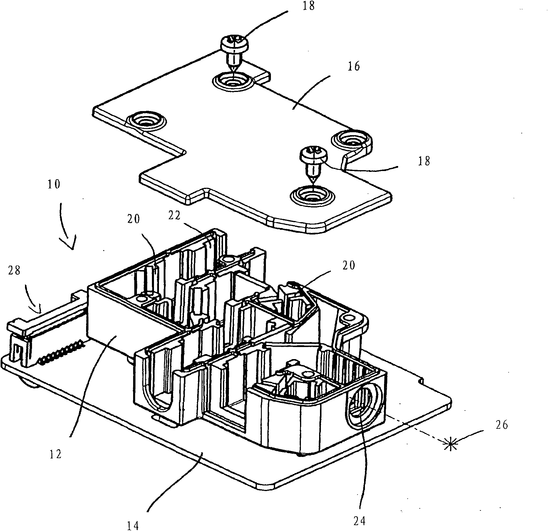
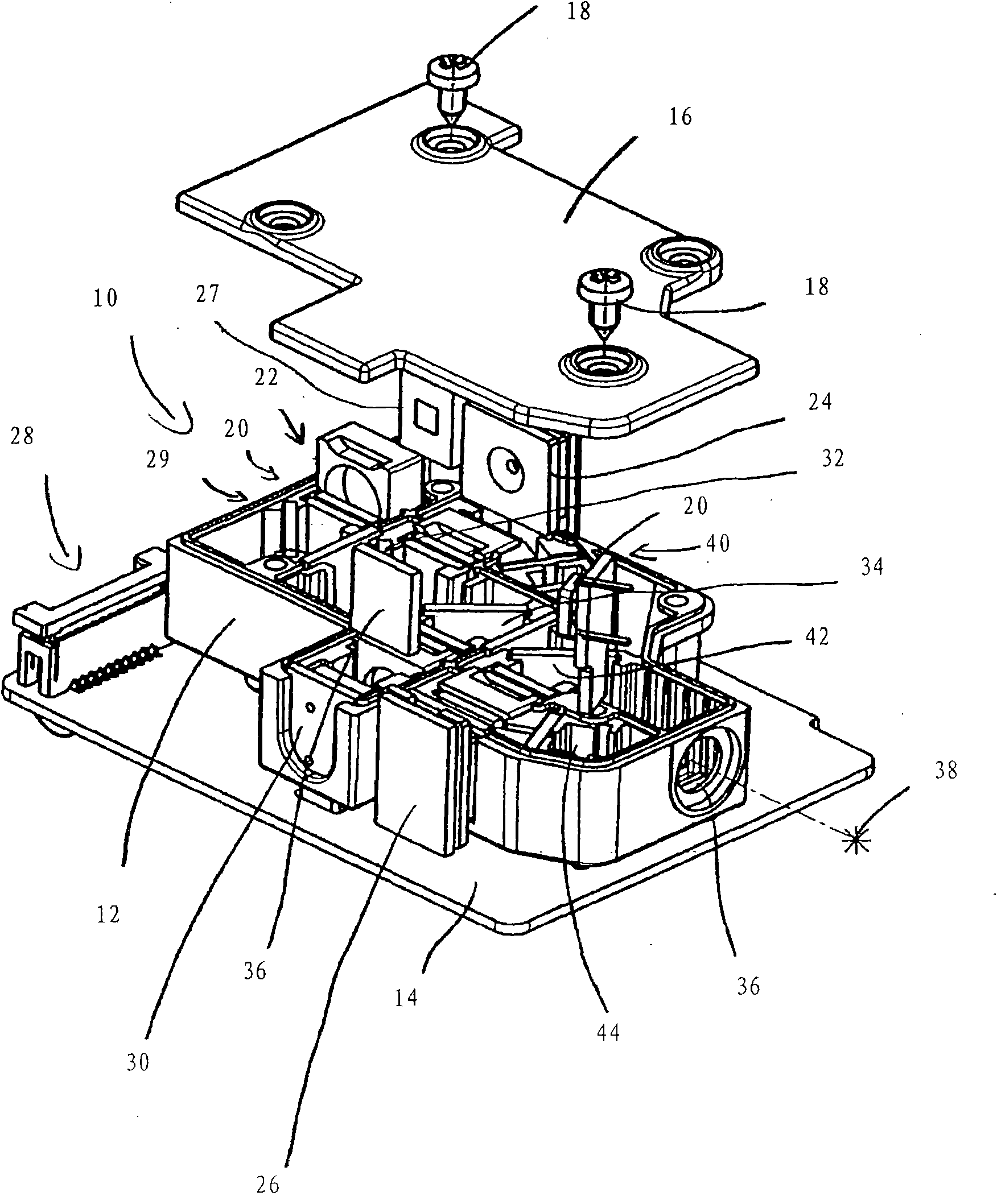
[0100] figure 1 A monolithic electro-optical module 10 serving as a main part of an optical measuring instrument and an optical measuring instrument according to the invention are shown in an unassembled state.

[0101] The monolithic module comprises a mechanical platform 12 forming a unit for carrying all necessary optical and electronic components, such as the source of the electromagnetic beam and the sensors to detect the output of any interaction between the emitted electromagnetic beam and the specimen to be investigated.

[0102] The mechanical platform 12 is disposed on a printed circuit board (PCB) 14 carrying electronic components and conductive traces. Additionally, a cover plate 16 is provided to cover the mechanical platform 12 and protect components within the mechanical platform 12 (not shown in this view). Cover plate 16 may be secured t...


PUM

PropertyMeasurementUnit
Gain coefficientaaaaaaaaaa

Abstract

The invention provides for an optical measuring instrument and a measuring device. The optical measuring instrument for investigating a specimen contained in a sample comprises at least one source forproviding at least one electromagnetic beam intended to irradiate the sample and to interact with the specimen within the sample, at least one sensor for detecting an output of the interaction between the specimen and the electromagnetic beam, an integrally formed mechanical bench for the optical and electronic components, a sample holder for holding the sample, wherein the at least one source, the at least one sensor, and the mechanical bench are integrated in one monolithic optoelectronic module and the sample holder can be connected to this module.

Description

technical field [0001] The invention relates to an optical measuring instrument and an optical measuring device. Furthermore, the invention provides a method for performing optical measurements and a computer program for implementing the method. Background technique [0002] Optical measuring instruments and methods of performing optical measurements are known. [0003] Lateral flow immunoassays, as an example of an optical measurement technique, have in the past become valuable tools for a variety of diagnostic applications. The most notable reason for this development is that these tools are reasonably sensitive and specific for many applications, and the results are obtained quickly, because they are applied directly to the sample without preceding time-consuming sample preparation steps. Lateral-flow immunoassays are easy to perform, and they do not require reading equipment, so they are low-cost and mobile. [0004] However, like every technique, lateral flow immunoa...

Claims


Application Information

Patent Timeline
Patent Type & Authority Applications(China)
IPC IPC(8): G01N21/64
CPCG01N2201/024G01N21/8483G01N21/255G01N21/645G01N2201/0228
Inventor 罗曼·格鲁勒康拉德·福尔斯蒂克
Owner 凯杰康士坦茨湖有限责任公司
Why Eureka
Try Eureka