
Dynamo for faucet

一种发电机、水龙头的技术,应用在水力发电、反作用式发动机、发动机元件等方向,能够解决阻碍环绕线圈交链磁路、线圈效率、发电量降低等问题

Inactive Publication Date: 2010-03-31
TOTO LTD
View PDF1 Cites 6 Cited by
  • Summary
  • Abstract
  • Description
  • Claims
  • Application Information

AI Technical Summary

Problems solved by technology

[0004] The permanent magnet used in the "axially arranged" generator is composed of alternate magnetization of N pole and S pole on the end face in the direction approximately perpendicular to the radial direction. If the yoke near the inductor directly below the adjacent magnetic pole A short circuit of the magnetic circuit between them will hinder the formation of the interlinked magnetic circuit around the coil, resulting in the reduction of coil efficiency and power generation.

Method used


Image

  • Dynamo for faucet
  • Dynamo for faucet
  • Dynamo for faucet

Examples


Embodiment Construction

[0041] Embodiments of the present invention will be described below with reference to the drawings.

[0042] In each figure, the same code|symbol is attached|subjected to the same component.

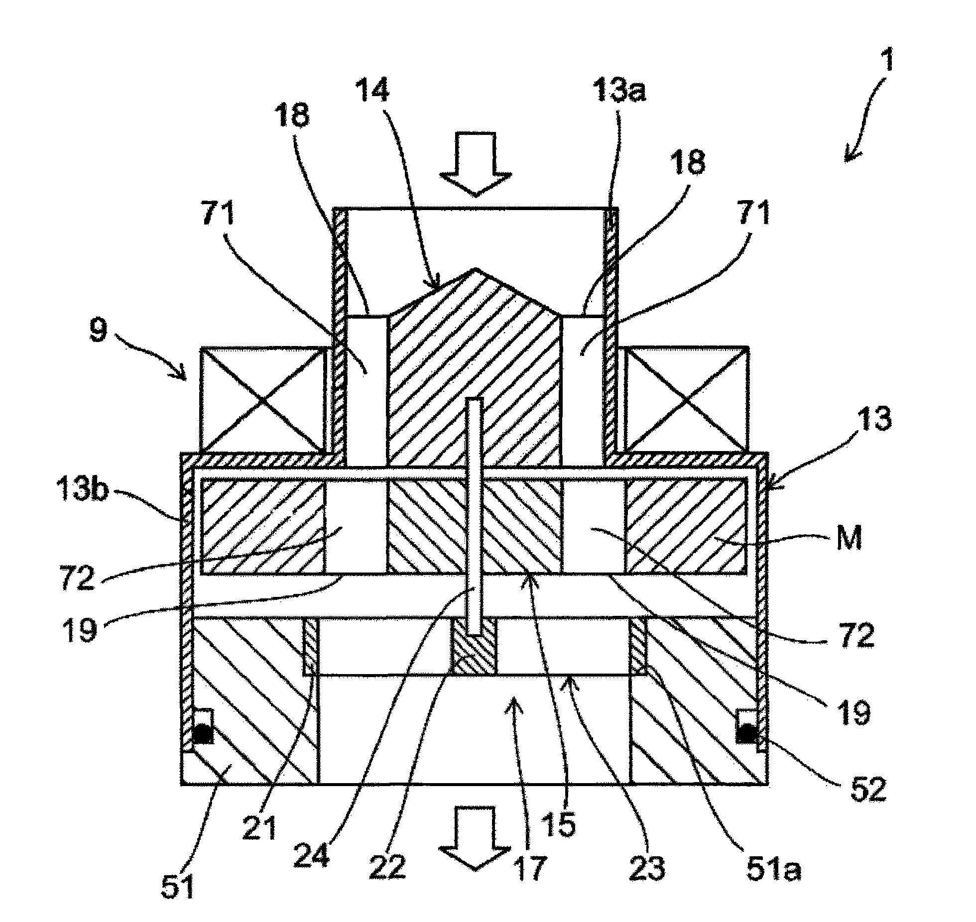
[0043] figure 1 It is a schematic sectional view for demonstrating the generator 1 which concerns on embodiment of this invention.

[0044] Figure 4 It is a schematic perspective view for explaining the pre-rotation vane 14 , the rotor vane 15 , and the bearing 17 of the generator 1 . Figure 4 (a) shows the case where the rotor blade ring 15a is not provided, Figure 4 (b) shows the case where the rotor blade ring 15a is provided.

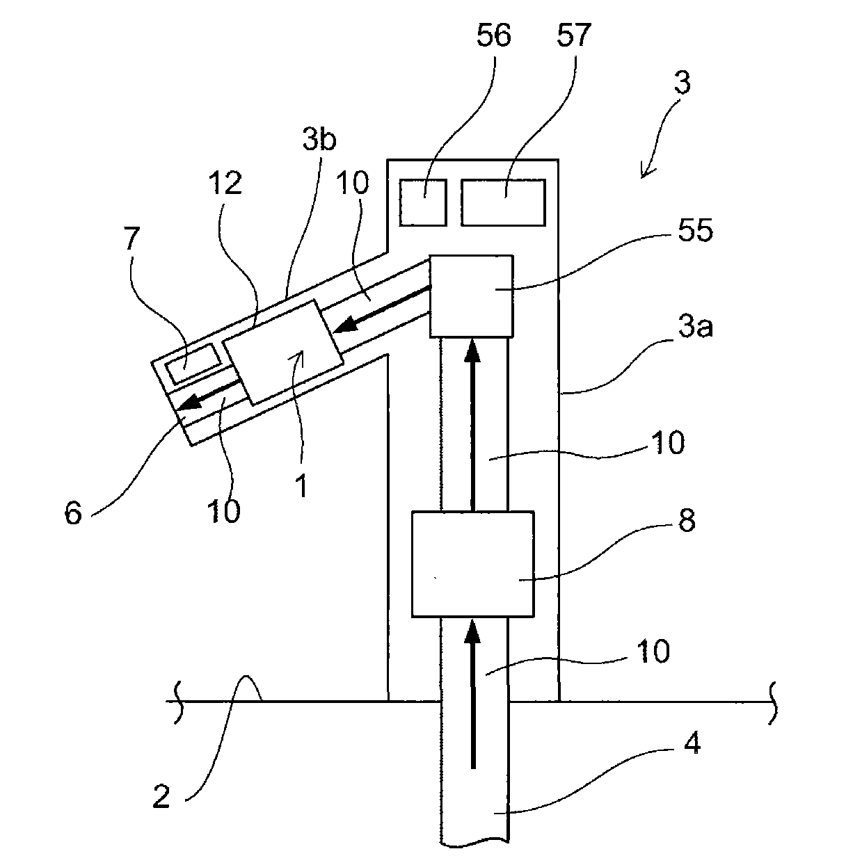
[0045] Such as figure 1 As shown, the generator 1 mainly includes a cylinder 13, a pre-rotation vane 14, a moving vane 15, a magnet M, a stator 9, and a sealing member 51, all of which are housed in a housing 12 (see image 3 )middle. In addition, arrows placed above the pre-rotation vane 14 and below the sealing member 51 indicate the water flow dire...


PUM


Abstract

A dynamo for faucet includes a rotor blade provided in a water supply channel, annular magnets rotatable integrally with the rotor blade, and a stator having a coil provided oppositely to the end faceof the magnet in the direction substantially perpendicular to the radial direction thereof, a plurality of inductors arranged along the circumferential direction while spaced apart from each other between the end face of the magnet and the coil, and a yoke provided around the coil continuously to the inductor. The axial direction of the rotor blade is substantially parallel with the water supplychannel, and the annular magnets are magnetized alternately with N pole and S pole on the end face in the direction substantially perpendicular to the radial direction along the circumferential direction. The yoke is cut, as a cut part, at a position close to the distal end of the inductor in one end of the yoke opposing the circumferential surface of the coil and provided with the inductor so that the portion of the yoke located closely to the distal end of the inductor is formed to recede relatively from an area of the magnet capable of magnetic induction.

Description

technical field [0001] The aspect of this invention generally relates to the generator for faucets which generate|occur|produces electric power using the flow of supply water. Background technique [0002] Conventionally, there is known an automatic water faucet device that automatically discharges water from the faucet when a sensor detects a hand extending under the faucet. In addition, there is also known a device in which a small generator is arranged on the flow path of such an automatic faucet device, and the power obtained by the generator is stored to supplement the power of the circuits such as the above-mentioned sensors (for example, refer to Patent Document 1). . [0003] Such generators can be classified into "radially arranged" generators in which coils are arranged outside the permanent magnets in the radial direction (for example, refer to Patent Document 1 Figure 4 ); and a generator of "axial arrangement" in which coils are disposed in a manner that is su...

Claims


Application Information

Patent Timeline
Patent Type & Authority Applications(China)
IPC IPC(8): H02K21/24E03C1/05F03B17/06H02K7/18
CPCH02K21/24Y02E10/223H02K7/1823Y02E10/28E03C1/0404F03B3/04F03B3/126F05B2220/20Y02E10/20
Inventor 小野寺尚幸佐藤知子黑石正宏畠山真清水刚
Owner TOTO LTD
Features
  • Generate Ideas
  • Intellectual Property
  • Life Sciences
  • Materials
  • Tech Scout
  • Unparalleled Data Quality
  • Higher Quality Content
  • 60% Fewer Hallucinations
Learn More