
Rubber-metal spherical hinge provided with hard stop catch on end face

A ball hinge and stopper technology, applied in the direction of elastic shock absorbers, etc., can solve the problems of high manufacturing cost, complicated process realization, uneven radial stiffness, etc., and achieve the effect of easy manufacturing, lower manufacturing cost and guaranteed uniformity

Active Publication Date: 2010-04-14
ZHUZHOU TIMES NEW MATERIALS TECH
View PDF0 Cites 12 Cited by
  • Summary
  • Abstract
  • Description
  • Claims
  • Application Information

AI Technical Summary

Problems solved by technology

[0005] 1. Open a hole between the jacket and the mandrel. The inside of the hole is used to place a hard stop. This structure requires a hole between the jacket and the mandrel. The stiffness in the direction of the hole and the stiffness in the direction of the non-hole It is inconsistent, resulting in anisotropic inhomogeneity of radial stiffness, and the manufacturing cost of this structure is relatively high, and the process is more complicated to realize
[0006] 2. The hard stop is placed in the middle of the jacket. The uniformity of the radial stiffness of this structure in the radial direction is very good, but the assembly process of the ball joint is very complicated and the manufacturing cost is also high

Method used


Image

  • Rubber-metal spherical hinge provided with hard stop catch on end face
  • Rubber-metal spherical hinge provided with hard stop catch on end face
  • Rubber-metal spherical hinge provided with hard stop catch on end face

Examples


Embodiment Construction

[0015] The accompanying drawings show an embodiment of the present invention, and the present invention will be further described below in conjunction with the accompanying drawings.

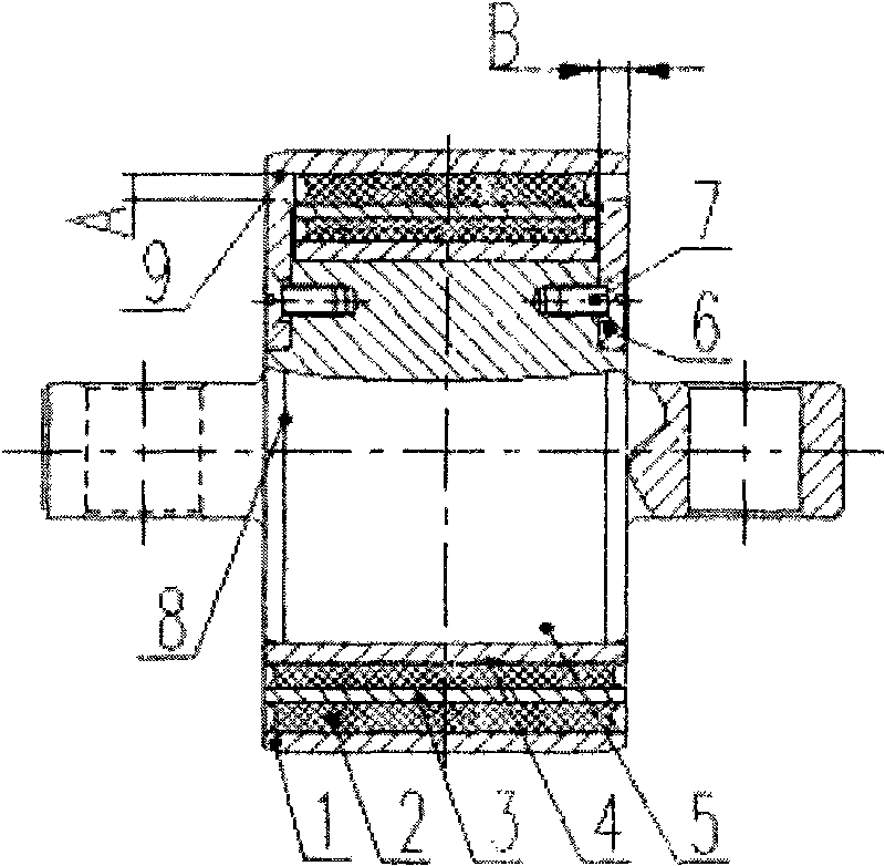
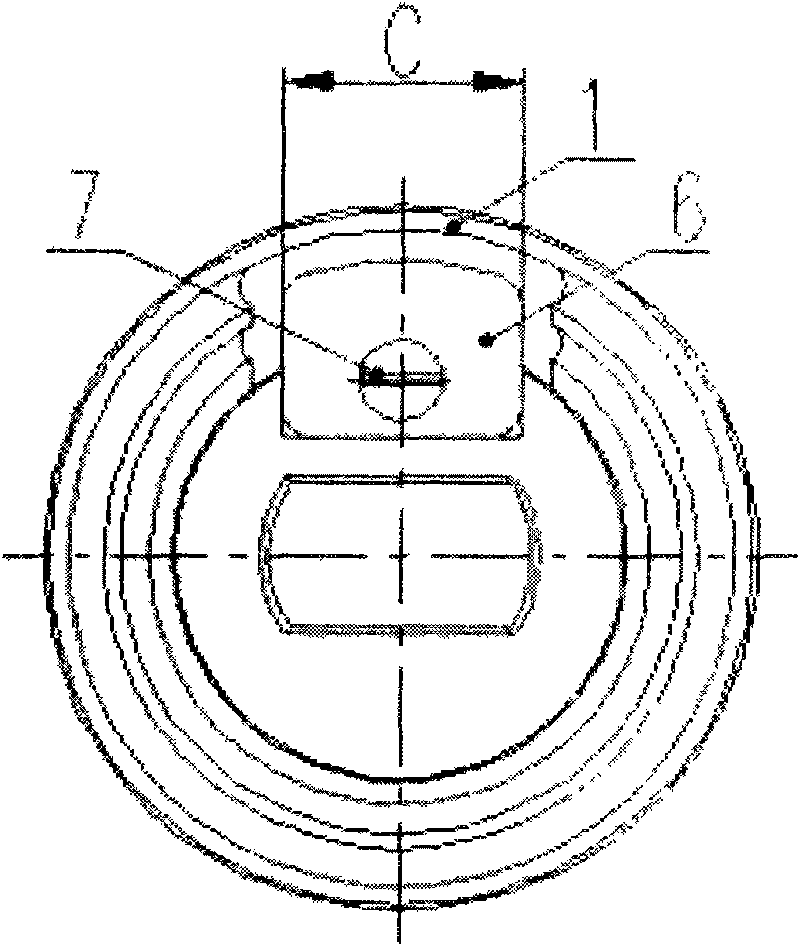
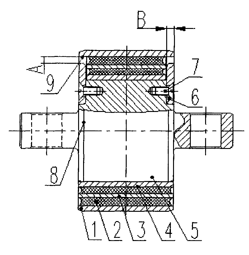
[0016] It can be seen from the accompanying drawings that the present invention is a metal sleeve-hard stopper-rubber combined ball joint, which places the hard stopper on the end face of the mandrel, and installs it through fasteners after the ball joint is made. On the two ends of the elastic damping part of the spherical hinge mandrel, and ensure that there is an axial gap between the top of the hard stop and the outer shell of the elastic damping part, when the outer shell of the elastic damping part moves radially relative to the hard stop When the gap is exceeded, it is limited.

[0017] The ball joint with a radial limit device includes a metal outer sleeve 1, an elastic rubber body 2, a spacer 3, a metal inner sleeve 4, a mandrel 5, a radial hard stop 6 and a fastener 7 of the ball joint...


PUM


Abstract

The invention relates to radial limiting method and device of a spherical hinge. A hard stop catch is placed on the end face of a core shaft and is installed at two end faces of an elastic vibration damping part of the core shaft of the spherical hinge through a fastener after the spherical hinge is manufactured, and a radial gap is ensured to be left between the top of the hard stop catch and an outer sleeve of the elastic vibration damping part. When radially moving relative to the hard stop catch to exceed the gap, the outer sleeve of the elastic vibration damping part is limited. The spherical hinge comprises the core shaft and the elastic vibration damping part, wherein the elastic vibration damping part is a rubber-metal composite element which is formed by compounding a metal outer sleeve, a metal inner sleeve, an interlayer and elastic rubber; a rubber part is integrally vulcanized with the metal outer sleeve and the metal inner sleeve together; a radial hard stop catch is arranged on the inner face of the outer sleeve end of an elastic part; the radial hard stop catch of the spherical hinge is installed on two end faces of the core shaft close to the elastic vibration damping part; and a gap exists between the radial hard stop catch of the spherical hinge and the inner surface of the outer sleeve of the elastic part. The invention can prevent the outer sleeve and the core shaft of the spherical hinge from generating larger relative displacement when a rubber layer is damaged.

Description

technical field [0001] The invention is a damping component for a rail vehicle, specifically a damping spring for vehicle motor suspension, which is mainly installed on the upper end of a vertical rod of a linear motor to connect the vertical rod and the beam of the linear motor. technical background [0002] The linear motor is connected to the beam of the linear motor through five vertical rods, and the vertical rod is connected to the beam of the linear motor through a rubber metal ball joint. The rubber ball joint supports the weight of the linear motor and absorbs the vibration generated during the traction process of the linear motor. [0003] For the sake of safety, it is required that once the rubber layer of the ball joint is damaged and fails, the linear motor is not allowed to exceed the specified vertical displacement, so the ball joint is required to bear the role of limit at the same time. [0004] At present, there are two modes of radial limit: [0005] 1. O...

Claims


Application Information

Patent Timeline
Patent Type & Authority Applications(China)
IPC IPC(8): F16F7/12
Inventor 罗承俊冯万盛荣继刚张亚新
Owner ZHUZHOU TIMES NEW MATERIALS TECH
Learn More